Although the DARC smelt team has been working towards a historical era smelt, AIR has remained a major stumbling block. Use of a straight Viking Age blacksmith's bellows clearly does not push enough air volume to produce the type of bloom found in the archaeology. Getting enough air via an electric blower is clearly not historical. This whole problem will one of the research projects for this winter (expect further posts as the work proceeds).
We have been making due with a circa 1960's vintage vacumn cleaner blower. This is tough, but frankly older than some of our team members! Although we now have a second such blower rigged, there have been tense moments in recent smelts when the primary blower has stopped for one reason or another. (As I myself am just slightly older than this piece of equipment - I feel its pain!) To that end, we are going to invest in a brand new industrial blower for the upcoming year.
I had the following recommendation by Skip Williams - Good Advice which I pass along to my readers...
We've been using blowers made by AMETEK. They come in two varieties
1) a multistage vane pump - super quiet - fixed air output
2) brushless DC moter - with variable output
We have both kinds. For Full Scale smelting we generally use the
fixed output variety with an air dump valve at the tuyere. For any
research with teeny-tiny furnaces it is nice to be able to turn the
fan down to just a few CFM... so I use the variable type. I've found
that the 63 CFM blowers produce much more air than I can use.
These blowers are available cheaply from online 'surplus' stores.
Just Google "Ametek Blower". BTW. the retail price is over $1000
Try this one:
http://www.73.com/a/0701.shtml
50CFM 115VAC/60HZ BLOWER
50 CFM BLOWER AMETEK #116246-04.
Motor is rated 115 VAC 1.9 amps60Hz / 3450 rpm. Ball bearing. Continuous duty. Thermally protected. Five-stage centrifugal design. The blower will move 50 cfm
of air at 0" of water-static pressure. Vacuum rating is 10 cfm at 16" of
water-vacuum.
Circular inlet has a 1.675" I.D. and a 1-3/4" O.D.
The circular outlet has a 1.6" I.D. and a 1-3/4" O.D.
A rectangular mounting foot is located on the bottom of the circular fan body. The
foot is 3-3/4" wide x 2-1/2" deep. Four tapped mounting holes are located in the corners of the foot The holes are tapped 1/4"X20 tpi. The hole centers are 1-3/4" apart (front to rear)and are 3" apart side to side)
(includes starting capacitor).
Dimensions:9-3/4" wide x 9" deep (front to back) x 10" high.
RFE $119.00 Ea.
That list price is in US funds, and does not include shipping.
Thursday, November 29, 2007
Tuesday, November 27, 2007
Martin Course Smelt
Martin Smelt Course - 11/25/07
This is a brief overview of the smelt undertaken as a course over the weekend of November 24 / 25, 2007 by Peter Martin and friends. Note that this report lacks certain details on the exact smelt sequence (others took the data there).
Saturday consisted of an overview lecture, construction of the smelter, plus preparation of the materials. One important difference with this smelt is that it took place INSIDE, on the main shop floor. The space is dirt floored with poured concrete walls and a 20 peak to the roof. This was done because of the start of winter weather (daytime temperatures just below freezing and with 4 inches of snow down).
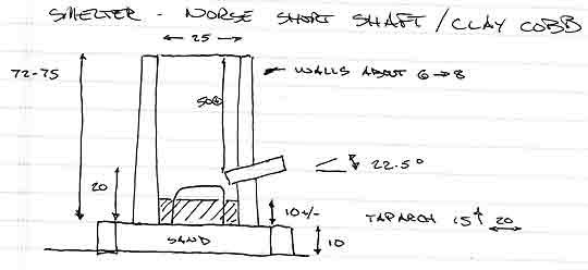
SMELTER: standard Norse Short Shaft - clay cobb
Height: 72 - 75 cm
Diameter: 25 cm (internal)
Thickness : 6 - 8 cm (somewhat variable)
Tuyere: 2.5 cm ID, standard ceramic tube
Position: 22.5 down angle / about 4 cm proud inner wall
Base: about 10 cm below tuyere
The smelter was constructed on a low plinth, a line of standard bricks filled with tamped sand. The shape of the smelter was to our standard profile, controlled by using two sheet metal forms for inner and outer diameters. In this case the clay was mixed up somewhat on the wet side and was not compacted as evenly as normal (first time builders). The cob was made of commercial ball clay mixed about 50/50 by volume with chopped straw (no sand added). The structure was left overnight with the sheet metal forms in place to allow the clay to stabilize.
After the metal forms were removed, the structure was straightened and tap arch and tuyere cut into the walls. It was obvious that the soft clay was starting to slump, so a split hardwood fire was started inside. The internal base level was allowed to develop from ash and small charcoal remnants. A much longer than normal pre-heat sequence was undertaken to dry the clay - twice the normal at over two hours. Only the last 15 minutes was under the influence of the blower at its lowest setting.
The primary ore material was commercial taconite pellets, sourced from Defasco in Hamilton Ontario. These had been previously roasted in a gas forge and then water quenched (to ease breaking). The team crushed 36 lbs of this material to the normal 'rice to half pea' size. In keeping with some recent observations by Lee Sauder, a further 4 lbs of poor quality Virginia rock ore was set aside as a seed charge. The expectation here was that the higher silica content of this material would speed the formation of the slag bowl. In total 40 lbs of the two ores was used.
As usual, the main sequence started by filling the furnace with rough carcoal, followed up with additions of graded fuel (2.5 cm pieces). Air was set at roughly 750 litres per minute. This number is only an estimate, as the first blower failed part way through the smelt and had to be replaced with the standby unit. (There are no exact measurements for the second blower, but sound and consumption rates remained constant - suggesting close to the same volumes.) From the first, the smelter ran hot, with initial consumption of the standard 10 litre (about 4 lb) measure of charcoal in the range of 6 minutes. Significantly, the entire internal volume of the smelter very quickly ignited, shortening the time required to first ore addition.
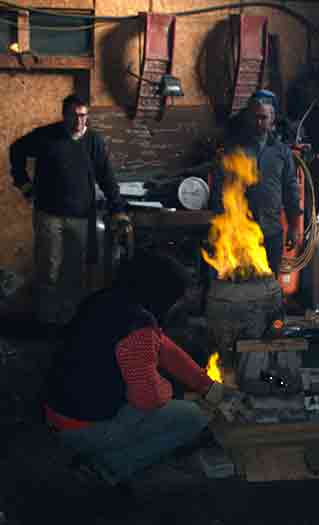
About half way into the main smelt sequence
A fairly standard ore and charcoal sequence was followed. The material of the seed charges was added as 'slugs'. Time was allowed for this material to hit tuyere level before starting the main ore charges. A standard time internal was maintained at roughly 8 - 9 minutes per fixed charcoal bucket. As has been seen in the past, the furnace accepted ever larger volumes of ore inside those charcoal charges, in this case peaking at 5 scoops (about 2 kg) or about 1 : 1 ore to charcoal by weight. The alloted ore was added in roughly 3 hours. Latter in the sequence, the smelter make several self tapping leaks of slag. This proved to be transitional, thin and dark but with not enough iron content to be magnetic. As much as a teaching tool as anything else, this material was re-cycled. Over the course of the smelt there was no problem with too high slag levels. The tuyere only required rodgering out on two occasions.
Time was again given for the last of the ore to fall to tuyere level, then a last 'shock charge' of 3 scoops (about 1 kg) was added as a single slug. This was covered with a last two buckets of charcoal, then the furnace was allowed to start to burn down.
The furnace had been set up with a large enough tap arch to allow for a bottom extraction, but the team wanted to use a top extraction method. To that end, the interior level of burning charcoal was allowed to drop down to roughly 1/3 of the volume before extraction was started.
Air was cut back to a lower level (about enough to keep the interior temperatures constant) and the charcoal covering the slag bowl was scooped away. An attempt was made to loosen the bloom with the log 'thumper' but this proved less than normally effective. The tap arch block was pulled away, which also removed about 1/3 of the lower slag bowl which was stuck to the clay. The lower level of ash and some sand was raked out, making use of the thumper from the top more effective. With some use of a long chisel tipped rod it was possible to loosen and grab free the bloom with tongs.
The furnace had more fresh charcoal added and air blast returned. In this way it was possible to re-heat the bloom, allowing for several working heats to be taken. First, the loose mother was struck off using heavy hammers and an anvil set on the floor. Some attempt was made to compress the bloom in latter heats, but the smelter-as-forge set up proved not the best for getting back up to the higher heats required. In the end it was decided to use our remaining energies to section the bloom, a process that itself took three heating cycles to accomplish.
The bloom being re-heated after initial hammering
The finished bloom had a somewhat a lumpy and fragmented consistency. Spark tests after it cooled showed it has a range of carbon contents - from a good soft iron on one side through to a mid carbon on the opposite (guestimated at about .3 carbon) The total size of the finished bloom (before cutting) was 12 lbs. This is a 30% return on ore used.
In all a text book smelt, which proved perfect as a teaching experience for the team members. The furnace preformed perfectly, with no significant problems over the smelt. The sequence ran just as predicted, with end results almost exactly as expected.
This is a brief overview of the smelt undertaken as a course over the weekend of November 24 / 25, 2007 by Peter Martin and friends. Note that this report lacks certain details on the exact smelt sequence (others took the data there).
Saturday consisted of an overview lecture, construction of the smelter, plus preparation of the materials. One important difference with this smelt is that it took place INSIDE, on the main shop floor. The space is dirt floored with poured concrete walls and a 20 peak to the roof. This was done because of the start of winter weather (daytime temperatures just below freezing and with 4 inches of snow down).
SMELTER: standard Norse Short Shaft - clay cobb
Height: 72 - 75 cm
Diameter: 25 cm (internal)
Thickness : 6 - 8 cm (somewhat variable)
Tuyere: 2.5 cm ID, standard ceramic tube
Position: 22.5 down angle / about 4 cm proud inner wall
Base: about 10 cm below tuyere
The smelter was constructed on a low plinth, a line of standard bricks filled with tamped sand. The shape of the smelter was to our standard profile, controlled by using two sheet metal forms for inner and outer diameters. In this case the clay was mixed up somewhat on the wet side and was not compacted as evenly as normal (first time builders). The cob was made of commercial ball clay mixed about 50/50 by volume with chopped straw (no sand added). The structure was left overnight with the sheet metal forms in place to allow the clay to stabilize.
After the metal forms were removed, the structure was straightened and tap arch and tuyere cut into the walls. It was obvious that the soft clay was starting to slump, so a split hardwood fire was started inside. The internal base level was allowed to develop from ash and small charcoal remnants. A much longer than normal pre-heat sequence was undertaken to dry the clay - twice the normal at over two hours. Only the last 15 minutes was under the influence of the blower at its lowest setting.
The primary ore material was commercial taconite pellets, sourced from Defasco in Hamilton Ontario. These had been previously roasted in a gas forge and then water quenched (to ease breaking). The team crushed 36 lbs of this material to the normal 'rice to half pea' size. In keeping with some recent observations by Lee Sauder, a further 4 lbs of poor quality Virginia rock ore was set aside as a seed charge. The expectation here was that the higher silica content of this material would speed the formation of the slag bowl. In total 40 lbs of the two ores was used.
As usual, the main sequence started by filling the furnace with rough carcoal, followed up with additions of graded fuel (2.5 cm pieces). Air was set at roughly 750 litres per minute. This number is only an estimate, as the first blower failed part way through the smelt and had to be replaced with the standby unit. (There are no exact measurements for the second blower, but sound and consumption rates remained constant - suggesting close to the same volumes.) From the first, the smelter ran hot, with initial consumption of the standard 10 litre (about 4 lb) measure of charcoal in the range of 6 minutes. Significantly, the entire internal volume of the smelter very quickly ignited, shortening the time required to first ore addition.
A fairly standard ore and charcoal sequence was followed. The material of the seed charges was added as 'slugs'. Time was allowed for this material to hit tuyere level before starting the main ore charges. A standard time internal was maintained at roughly 8 - 9 minutes per fixed charcoal bucket. As has been seen in the past, the furnace accepted ever larger volumes of ore inside those charcoal charges, in this case peaking at 5 scoops (about 2 kg) or about 1 : 1 ore to charcoal by weight. The alloted ore was added in roughly 3 hours. Latter in the sequence, the smelter make several self tapping leaks of slag. This proved to be transitional, thin and dark but with not enough iron content to be magnetic. As much as a teaching tool as anything else, this material was re-cycled. Over the course of the smelt there was no problem with too high slag levels. The tuyere only required rodgering out on two occasions.
Time was again given for the last of the ore to fall to tuyere level, then a last 'shock charge' of 3 scoops (about 1 kg) was added as a single slug. This was covered with a last two buckets of charcoal, then the furnace was allowed to start to burn down.
The furnace had been set up with a large enough tap arch to allow for a bottom extraction, but the team wanted to use a top extraction method. To that end, the interior level of burning charcoal was allowed to drop down to roughly 1/3 of the volume before extraction was started.
Air was cut back to a lower level (about enough to keep the interior temperatures constant) and the charcoal covering the slag bowl was scooped away. An attempt was made to loosen the bloom with the log 'thumper' but this proved less than normally effective. The tap arch block was pulled away, which also removed about 1/3 of the lower slag bowl which was stuck to the clay. The lower level of ash and some sand was raked out, making use of the thumper from the top more effective. With some use of a long chisel tipped rod it was possible to loosen and grab free the bloom with tongs.
The furnace had more fresh charcoal added and air blast returned. In this way it was possible to re-heat the bloom, allowing for several working heats to be taken. First, the loose mother was struck off using heavy hammers and an anvil set on the floor. Some attempt was made to compress the bloom in latter heats, but the smelter-as-forge set up proved not the best for getting back up to the higher heats required. In the end it was decided to use our remaining energies to section the bloom, a process that itself took three heating cycles to accomplish.
The finished bloom had a somewhat a lumpy and fragmented consistency. Spark tests after it cooled showed it has a range of carbon contents - from a good soft iron on one side through to a mid carbon on the opposite (guestimated at about .3 carbon) The total size of the finished bloom (before cutting) was 12 lbs. This is a 30% return on ore used.
In all a text book smelt, which proved perfect as a teaching experience for the team members. The furnace preformed perfectly, with no significant problems over the smelt. The sequence ran just as predicted, with end results almost exactly as expected.
Saturday, November 24, 2007
Winter Considerations
This last week I was invited to give a couple of lectures at Laurier University in Waterloo. Our smelt team has made friends with a couple of archaeology professors there - Dean Knight and Ron Ross.
The lecture of Dr Knight's ancient technologies course was on iron smelting (as might be suspected). At dinner, the lot of us got talking about the DARC experimental series, and what direction our future work might take.
Obviously one major thrust is the continuing series working towards a reconstruction of the Icelandic turf walled construction as excavated at Hals by Kevin Smith. This is primarily a furnace problem, and outside of the mechanics of gathering of the required grass sods, * seems * pretty straight forward. (The outlines of this project have been seen in earlier posts here.)
At this point, several deep background research projects are called for. These are mainly to take our practical experiences and frame them up against what is known from the archaeology:
1) Overview of Blooms and Smelters
Right now our best single resource for historic prototypes is Pliener's 'Iron in Archaeology'. Unfortunately most of the information we really need is buried in hard to find and harder to access field reports and journal articles. What is needed is a simple table style listing of the data from individual finds. Location / measurements / dates. Especially a cross linking of smelters against blooms and source ores.
2) Overview of Experimental Smelts
There is no standard set of records being kept by individual smelt teams. The arrangement of furnaces / air systems / ore against bloom production is often hard to pin down. Not everyone keeps measurements on things like air volumes. Again what would be extremely helpful would be a simple table style listing of the related data.
3) Air Systems
Our own team has developed certain impressions about what form historic air systems may have taken. A formal consideration of the theoretical footprint of the various alternatives should be written. At this point we should be able to estimate (if not clearly illustrate) the impact of the various possible systems in terms of things like debris fields.
Each one of these represents at least a potential journal article, if not a full blown academic paper (maybe a thesis!). A number of our close correspondents and advisors have been suggesting that we should be working to publish some of our experiences and conclusions.
Something to keep me inside next to the wood stove come January and February...
Wednesday, November 21, 2007
Extending Asumptions
(Blended from a couple of posts to NORSEFOLK)
"...Note the Throndjem woman's bead necklace. She (a re-enactor) told me that the necklaces were rarely symmetrical. Each bead 'told its own story' as to where and when it was collected or bought or traded...."
(name deliberately removed to protect the inocent)
Not a remote chance that this statement can be any more than a single person's imagination. In some cases it may be possible to tell from location in an excavation the order of the beads, but in most cases these have so widely scattered as the body settles that the original order can only be guessed at. If your sources are museum presentations - often the order has been 'reconstructed' at the taste of the conservator.
As to why a specific bead has gone where - it is absolutely impossible to attribute order to some cultural activity.
Note that I'm not discussing the details of bead necklace construction, save as an example of a larger concept in interpreting objects. (Karen mentioned this, as she and Neil and Meghan and I have much hashed over the topic of beads and interpretations frequently).
There are a number of different ways a person could assemble the order of beads on to a string:
One most important variable would be the method of collecting the number. Purchased all at once - or collected over time (and perhaps space)?
Was the order static - or was it constantly being modified in terms of order and additions?
Is the combination in any way symmetrical? If so - what is the measure of balance? This is particularly important, because if you look at the use of semi-precious stones set on metal objects from the same time, you will see that 'balance' may be in terms of matching size / matching shape / and not as often matching colour / matching material.
Now there is absolutely no way that we can measure if bead order was determined by some sequence of applied memories in the mind of the owner. I suspect that this assertion was made on the basis of negative evidence - 'we see no other obvious order, so therefore the sequence is based on memories'. Could just as easily be totally random . Could be based on purchase order. Could be 'the strand broke and I was in too much of a rush to just get all the beads stuck on a strand again to bother'. Any of these others just as likely.
(Sandy, a researcher at the Frojel site in Gotland Sweden commented on some finds there.)
Sandy's description of the half blue / half silver strand illustrates an important point. (Going out on a pretty thin limb here) - It is most commonly seen that the order chosen by the Norse was much different than the order chosen by Victorian archaeologists - or that chosen by modern taste. I'm not attempting to get into the details of individual strands, as I have certainly NOT studied these in enough detail to present specific examples.
I comment on the underlaying concept - Take care applying modern opinions to historic details.
Tuesday, November 13, 2007
Beowulf / Shamol-wulf
I thought some of you would get a laugh out of this. The text found and forwarded to me by my wife Vandy. Remember those descriptions of pieces I had done for the long lost 'Outlander' film? Well everyone jumped on the bandwagon of our Anglo-Saxon Hero a while back. The lastest version is just hitting the theatres - and the * trailer * even looks like a bad video game...
From Antagony and Ecstasy, one of the movie review sites Vandy reads:
A cartoon is coming, || computer-created,
Generated on green-screen , || the graphics laid over.
Beowulf is the book || bound for the movies,
Retold by that rascal || Robert Zemeckis,
His camera is clumsy || compulsively gaudy.
The trailer is terrifying || a tragic misfire
Of video unviewable || and a valley uncanny,
The proud performers || plastic and ugly
Wednesday, November 07, 2007
Riverdale House - 2nd Install
On Tuesday (Nov 6) I installed the next two units of the Riverdale House railing project in Toronto

The third piece of the project was a half circle railing, 48 inches in diameter. To make both my fabrication, but more importantly transportation, easier, this was made in two pieces. A central leg was required to support the centre of the panel, so it proved fairly simple to run three bolts to joint the sections. This approach also allowed for a slight bit of flex to the curve during installation. Despite my butter fingers (after a three hour drive into Toronto) this unit fit its space exactly and proved quite quick and easy to secure into place. On subtle feature of this panel was that the leg piece had been hot punched with the names of the client and the date.

The fourth piece installed was the right hand (seen from the street) stair hand rail. This is the straight section. This proved a wee bit more of a problem to fit. Of course none of the angles on the wooden stairs proved to be at 90 degrees to each other - which can prove a series problem on a 9 foot long diagonal. In the end the railing fit fairly well. I had come prepared with some wooden shims (just in case). By lifting the lower support at the top deck level about a half inch, the rest of the support pieces fit pretty close. It proved possible to screw down the various attachment points tight to the existing stairs. I was quite pleased with how solid the finished hand rail was when fully attached with the lag screws.

This is a final view of the elements installed so far as they appear from the sidewalk. One panel remains - the curved hand rail for the left side stairs.
Further details can be seen on the main Wareham Forge web site :
www.warehamforge.ca/work-in-progress
The third piece of the project was a half circle railing, 48 inches in diameter. To make both my fabrication, but more importantly transportation, easier, this was made in two pieces. A central leg was required to support the centre of the panel, so it proved fairly simple to run three bolts to joint the sections. This approach also allowed for a slight bit of flex to the curve during installation. Despite my butter fingers (after a three hour drive into Toronto) this unit fit its space exactly and proved quite quick and easy to secure into place. On subtle feature of this panel was that the leg piece had been hot punched with the names of the client and the date.
The fourth piece installed was the right hand (seen from the street) stair hand rail. This is the straight section. This proved a wee bit more of a problem to fit. Of course none of the angles on the wooden stairs proved to be at 90 degrees to each other - which can prove a series problem on a 9 foot long diagonal. In the end the railing fit fairly well. I had come prepared with some wooden shims (just in case). By lifting the lower support at the top deck level about a half inch, the rest of the support pieces fit pretty close. It proved possible to screw down the various attachment points tight to the existing stairs. I was quite pleased with how solid the finished hand rail was when fully attached with the lag screws.
This is a final view of the elements installed so far as they appear from the sidewalk. One panel remains - the curved hand rail for the left side stairs.
Further details can be seen on the main Wareham Forge web site :
www.warehamforge.ca/work-in-progress
Thursday, November 01, 2007
Icelandic Smelt Two (report)
Stone Slab with Low Air
As was mentioned earlier, the DARC fall smelt was originally intended to follow on the development of an Icelandic style smelter.
Chamber size at Tuyere : 25 cm (front to back) x 35 cm (side to side)
Total furnace Height : 70 cm (random)
Shaft Height above Tuyere : 40 cm (minimum)
Height of Tuyere above base : 18 cm
Tuyere angle : starts at 26 down, latter shifted to 10 down
Tuyere size : standard 2.6 cm ID steel pipe
It was expected that the lower air volumes would greatly extend the time required for the smelt. Although better intentions were made, the pre-heat was started at our normal 9 AM, with primary smelt sequence started a bit after 10 AM. As normal, pre-heat was using wood splints, passive at the start and for the last 15 minutes or so using gentle air.
For this smelt, Neil was the iron master, with Ken working as lead hand. Darrell started the recording, with Ron Ross managing the latter half of this task.
It was decided to seed the smelt using the poorer quality Virginia Rock ore gathered last year by Darrel and Vandy. Although this material has proved to have too low an iron content, it was hoped that it would compensate for the lack of slag seen with earlier uses of the hematite grit. It was also expected that considerably less slag would be available inside this smelt with the use of stone instead of clay for the wall materials. In the end it proved we were overly conservative, and production of a suitable volume of slag would prove a problem.
With the lower consumption rates expected as a result of the lower air volume, it was also decided to limit the total amount of ore added. It was expected that this would only allow for the formation of a small bloom. The air volume used over this smelt was about 400 litres per minute - compared to the usual rate employed in past successful smelts at closer to 800 plus LPM. As was expected, the lower air greatly extended the time between additions of the standard 10 litre charcoal measure, which increased from a normal 8 minute average to closer to 22 minutes. The construction of the furnace had reduced the height of the reaction column from our normal 55 - 60 cm to closer to 40 cm. Still the theoretical 'drop time' for any individual particle of ore had been extended from a normal 25 - 30 minutes to double that - closer to 60 - 70 minutes. This was expected to produce problems in carbon control with the fine particles of the hematite grit.
Over the course of the smelt, the following totals were recorded:
Ore : 12.3 KG (10 kg hematite grit / 2.3 Virginia rock)
Charcoal : 170 litres + 6 kg ungraded fuel at start
Time : Main sequence = 6 hours
Generally the slower consumption rate lead to a much less frantic smelt sequence. It was obvious fairly early on that less slag was being produced. Although the furnace had been constructed as an 'incontinent' type, little slag was ever observed flowing from the slag bowl (even after the tap arch was opened latter in the smelt).
The next day the cold smelter was excavated, with a good photographic record made and representative samples collected. All the slag was collected, and the area was cleaned with the large magnet. The results of this work:
Weight of Slag : 3.5 KG
Weight of Reduced Ore (but poorly or not sintered) : 3 KG
Weight of 'Bloom' (fragments) : 2 KG
Conclusions:
1) The construction method using stone slabs with clay cobb sealing the joints is certainly viable. It is unlikely that the mica schist material would withstand a second firing without heavy replacement of the material at the normal hot zone above the tuyere. The stone in this area exhibits both considerable erosion and also a thick deposit of slag. Both of these effects should remain clearly visible in archaeological remains of this type.
2) The use of lower volume air requires considerable further experimentation to develop a truly successful sequence. As has been clearly demonstrated with both our earlier smelts and those of other experimenters - there is a (poorly understood) relationship between ore type and purity, smelter material and design, fuel preparation, and physical sequence. Those attempting smelts with low air volumes have great difficulty (if able at all) in producing large and well consolidated blooms.
3) In retrospect, it is most likely that both the content and the fine particle size of the hematite grit renders it quite unsuitable for use in any kind of low slag producing smelter. The extremely low silica content of the ore means that the formation of slag must come almost exclusively from the melting of the smelter walls. Although good results have been attained with this material in past smelts, this has always been inside those furnaces that have suffered considerable internal erosion.
As was mentioned earlier, the DARC fall smelt was originally intended to follow on the development of an Icelandic style smelter.
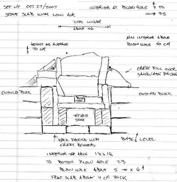 Front Elevation Drawing | On Friday, Darrell, Neil Peterson and Ken Cook worked on preparing the site and building the furnace. After a fairly wide ranging discussion, it was decided to work towards two experimental objectives: 1) Running a smelt with lower volumes of air. 2) Build the furnace using a stone slab construction method. The all stone slab construction was an extension of the Thanksgiving smelt, which had just the front section of the smelter made of stone. It also was a return to our very first group smelt (in spring 2002). The material on hand were relatively thin and randomly shaped pieces of mica schist. Despite some concerns about how water can create some potentially explosive effects on this stone when it is subjected to high temperatures, the material once again stood up extremely well. |
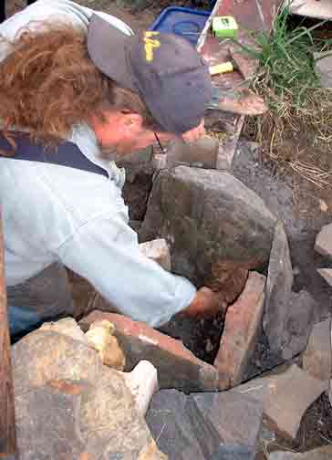 Ken at work sealing gaps with clay | The shape and proportions of the furnace was largely the result of the irregular shapes we had on hand. The overall height of the structure was also limited by the amount of stone available. Ken undertook most of the construction work, fitting the various slabs together as best he could. Considerable attention was focussed on the lower section and the front above tuyere level. The gaps between the slabs was filled with prepared clay cobb and sealed using wet waste clay. Once again the advantages of the straw fill in the cobb was obvious over the course of the smelt. The finished smelter actually most closely resembles the construction suggested for L'Anse aux Meadows. |
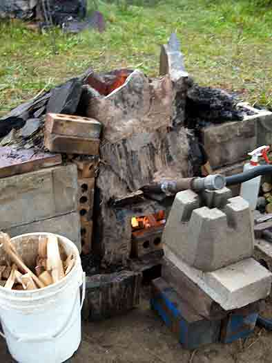 Furnace with tuyere in place - pre-heat phase | The finished furnace was deemed to be the ugliest one we had ever constructed! A large tap arch was blocked out by a nicely shaped stone. It was decided to use a bottom extraction method for this smelt. This resulted in a rather large lower section to the furnace, so a base level of charcoal fines was established. With the height of the tuyere elevated above ground level, but the total height of the furnace about the standard, the effective shaft height above the tuyere was reduced. Another wrinkle on the construction was a ledge of stone from the piece used to span over the tap arch. The tuyere was positioned so that it came just to the inner lip of this stone. In effect this placed the tip of the tuyere about 6 - 7 in from the line of the smelter interior wall. |
Chamber size at Tuyere : 25 cm (front to back) x 35 cm (side to side)
Total furnace Height : 70 cm (random)
Shaft Height above Tuyere : 40 cm (minimum)
Height of Tuyere above base : 18 cm
Tuyere angle : starts at 26 down, latter shifted to 10 down
Tuyere size : standard 2.6 cm ID steel pipe
It was expected that the lower air volumes would greatly extend the time required for the smelt. Although better intentions were made, the pre-heat was started at our normal 9 AM, with primary smelt sequence started a bit after 10 AM. As normal, pre-heat was using wood splints, passive at the start and for the last 15 minutes or so using gentle air.
For this smelt, Neil was the iron master, with Ken working as lead hand. Darrell started the recording, with Ron Ross managing the latter half of this task.
It was decided to seed the smelt using the poorer quality Virginia Rock ore gathered last year by Darrel and Vandy. Although this material has proved to have too low an iron content, it was hoped that it would compensate for the lack of slag seen with earlier uses of the hematite grit. It was also expected that considerably less slag would be available inside this smelt with the use of stone instead of clay for the wall materials. In the end it proved we were overly conservative, and production of a suitable volume of slag would prove a problem.
With the lower consumption rates expected as a result of the lower air volume, it was also decided to limit the total amount of ore added. It was expected that this would only allow for the formation of a small bloom. The air volume used over this smelt was about 400 litres per minute - compared to the usual rate employed in past successful smelts at closer to 800 plus LPM. As was expected, the lower air greatly extended the time between additions of the standard 10 litre charcoal measure, which increased from a normal 8 minute average to closer to 22 minutes. The construction of the furnace had reduced the height of the reaction column from our normal 55 - 60 cm to closer to 40 cm. Still the theoretical 'drop time' for any individual particle of ore had been extended from a normal 25 - 30 minutes to double that - closer to 60 - 70 minutes. This was expected to produce problems in carbon control with the fine particles of the hematite grit.
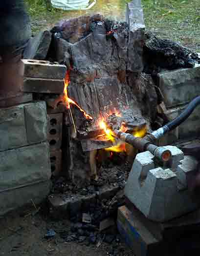 At the start of the burn down phase - note heat effects around tuyere | A secondary concern was the amount of penetration of air into the body of the smelter, again an expected effect of the lower volumes. Several times during the smelt, the depth of the heated zone was measured at tuyere level, This was done by the simple process of inserting a 3/8 diameter mild steel rod held horizontal to the ground through the blow hole. After about two minutes the rod was pulled out, and the colour of the rod used as a simple measure of heat. The rear 1/3 to 1/4 of the rod did not show any visible colour, indicating that the area of the furnace furthest from the tuyere had to be below 600 C. It was hoped that additions of ore would none the less drift towards the ignition area above the tuyere regardless. |
Over the course of the smelt, the following totals were recorded:
Ore : 12.3 KG (10 kg hematite grit / 2.3 Virginia rock)
Charcoal : 170 litres + 6 kg ungraded fuel at start
Time : Main sequence = 6 hours
Generally the slower consumption rate lead to a much less frantic smelt sequence. It was obvious fairly early on that less slag was being produced. Although the furnace had been constructed as an 'incontinent' type, little slag was ever observed flowing from the slag bowl (even after the tap arch was opened latter in the smelt).
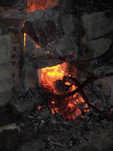 Neil reaches in with the bloom tongs, the bottom of the slag mass can be seen | Neil undertook the extraction, and was able to grab almost the entire slag mass as one piece. There was little liquid present, and not much remained inside the furnace (generally both bad signs). Kevin Jarbeau and Ken worked the surface quite lightly with the hammers. Almost immeadiately, the majority of the mass split away, obviously only slag. The material remaining was extremely granular and poorly sintered. Even under gentle strokes of the large hammers, it quickly broke into a number of golf ball size pieces. Although we had hoped for a least a small well consolidated bloom, it was clear our product was too fragile to work. |
The next day the cold smelter was excavated, with a good photographic record made and representative samples collected. All the slag was collected, and the area was cleaned with the large magnet. The results of this work:
Weight of Slag : 3.5 KG
Weight of Reduced Ore (but poorly or not sintered) : 3 KG
Weight of 'Bloom' (fragments) : 2 KG
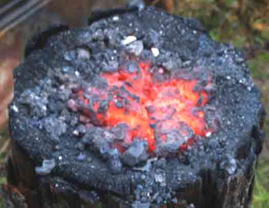 Fragments of still hot 'bloom' in place on the stump | Although the general opinion on the day was that the product of the smelt was in fact a high carbon cast iron, I personally had some doubts. In past uses of the hematite grit as an ore material, the results even with high air volumes always had a granular texture and a high carbon content. On Tuesday I attempted to work one of the denser fragments inside the coal forge. Knowing how fragile this granular material would be, the roughly goose egg piece was brought close to a welding heat and very gently worked with a wooden mallet. Even under the lightest of strokes it was not possible to do much more than just push the grains a bit closer together. I was not able to actually forge the material into any kind of solid piece. The end result was just a larger pile of smaller fragments. One piece (about 3 cm wide and about .5 thick) was compressed enough to have a noticeably flat surface, this was taken to the grinder for a spark test. The sparks produced were like those seen from a piece of high carbon tool steel (in the range of 1 % plus carbon content). It may prove possible to forge weld the fragments between two other slabs, but I was unable to work the material as it exists at this point. |
Conclusions:
1) The construction method using stone slabs with clay cobb sealing the joints is certainly viable. It is unlikely that the mica schist material would withstand a second firing without heavy replacement of the material at the normal hot zone above the tuyere. The stone in this area exhibits both considerable erosion and also a thick deposit of slag. Both of these effects should remain clearly visible in archaeological remains of this type.
2) The use of lower volume air requires considerable further experimentation to develop a truly successful sequence. As has been clearly demonstrated with both our earlier smelts and those of other experimenters - there is a (poorly understood) relationship between ore type and purity, smelter material and design, fuel preparation, and physical sequence. Those attempting smelts with low air volumes have great difficulty (if able at all) in producing large and well consolidated blooms.
3) In retrospect, it is most likely that both the content and the fine particle size of the hematite grit renders it quite unsuitable for use in any kind of low slag producing smelter. The extremely low silica content of the ore means that the formation of slag must come almost exclusively from the melting of the smelter walls. Although good results have been attained with this material in past smelts, this has always been inside those furnaces that have suffered considerable internal erosion.
Recording Smelting Slags
In the recent set of conversations backgrounding the Icelandic smelter series, Kevin Smith had asked me if we had been keeping any records of the amount of slag produced in each experiment. Truth is that although we have numbers for ore and bloom, we generally have no records for the amount of actual slag created. This is certainly a significant measurement, as there are very few metal blooms found - these were just too valuable considering the effort that had gone into creating them. Slag, on the other hand, is nothing more than a waste product, and an extremely durable one at that. There are literally tons of various slags, even within a single major historic iron producing site. Hals in Iceland, for example, Smith estimates there is some 5000 kg of waste slag. *
Slag remains are also used by modern researchers to estimate the probable yields of individual ancient smelts:
- First the ore utilized will be examined. Normally it is expected that there will be some 'slop' of ore to be found right close to the shaft of the furnace. (In our own work, we always end up dropping some ore material by accident as it is added to the top of the furnace.) By analyzing the relative iron content of that ore, an idea of the starting ratio of iron and other waste products (which will go to the slag) can be gathered. As has been pointed out by other contributers to the Early Iron discussion, there can be a couple of reasons why the ore materials found around a smelting area could be misleading. Ideally an experienced worker can make a good judgment of the suitability of an individual piece of ore at the gathering location. In many cases however, our own experience has shown that it is only after ore is roasted and broken for size that good quality may become apparent. Much of the ore found around a smelter site may actually represent this discarded material. Little (if any) of the actual ore utilized for the smelt itself may remain.
- Next the slag itself is analyzed for the remaining iron content. This can only supply the roughest of estimates for a number of reasons. The slag found will certainly vary considerably. The quality of the slag will change over the course of a smelt, from the viscous bubbly iron poor slag at the first stages, eventually becoming a thin hard iron rich material in the latter stages. Slag from any given point in the several hour process of the smelt can be quite different in composition. Even inside a large slag block from a single smelt event, there is certainly differences in iron content remaining at various points within the mass.
- Not only the ratio of iron and silica from the ore effect both volume and nature of the slag, but the materials and set up of the furnace itself have a major effect. Different wall materials will erode at quite different rates, and of course melted furnace walls are a major component of slag. Generally only the very base levels of a furnace will remain to be examined. so at best the amount of
- The mechanics of a single smelt will greatly effect the way slag may be scattered over a working area. In most cases these processes will change the visual appearance of the slag materials. Tap slag will have distinctive flow patterns for example. As hot slag is always a problem to the operators, discarded slags may be tossed some distance away from the working area. Our own experience has shown that a large amount of material may be pulled away from the slag bowl inside the smelter when the bloom is extracted, especially if a bottom extraction method is used. This material usually has a certain amount of partially sintered ore with it. (What Sauder & Williams call 'mother'.) This loose material is going to be found not at the smelter, but at the area where the initial consolidation of the hot bloom is to be carried out. This location is certain to be close by to the smelter, but may in fact be removed by a number of metres (and thus may not be uncovered by the excavation at all)
In our own experiments, we have generally been working with ores that run in the range of 60 - 70 % iron content. Our yields vary considerably, but run from about 30 - 40 % metallic bloom against ore.
For the last two smelts, we have attempted to recover as much of the slag produced as possible. This can hardly be considered a representative sample, more (and more detailed) observations need to be made.
Note : On Icelandic TWO, the 5 kg listed includes all materials recovered
- 1.7 kg small un-sintered fragments
- 2.3 kg badly sintered pieces (larger than 6 mm)
- 1 kg roughly golf ball sized denser pieces (considered true bloom)
Overall the material produced from this smelt proved too fragmented to forge, with an extremely high carbon content.
* With my recent focus on Hals in Iceland, I would be remiss if I did not provide readers with the reference for further details:
'Ore, Fire, Hammer, Sickle: Iron Production in Viking Age and Early Medieval Iceland'
Kevin Smith
Kevin has become a good friend and a close advisor to our experimental work over the years. He has contributed considerable depth to my understanding of the archaeology of iron smelting through our ongoing personal communications.
Slag remains are also used by modern researchers to estimate the probable yields of individual ancient smelts:
- First the ore utilized will be examined. Normally it is expected that there will be some 'slop' of ore to be found right close to the shaft of the furnace. (In our own work, we always end up dropping some ore material by accident as it is added to the top of the furnace.) By analyzing the relative iron content of that ore, an idea of the starting ratio of iron and other waste products (which will go to the slag) can be gathered. As has been pointed out by other contributers to the Early Iron discussion, there can be a couple of reasons why the ore materials found around a smelting area could be misleading. Ideally an experienced worker can make a good judgment of the suitability of an individual piece of ore at the gathering location. In many cases however, our own experience has shown that it is only after ore is roasted and broken for size that good quality may become apparent. Much of the ore found around a smelter site may actually represent this discarded material. Little (if any) of the actual ore utilized for the smelt itself may remain.
- Next the slag itself is analyzed for the remaining iron content. This can only supply the roughest of estimates for a number of reasons. The slag found will certainly vary considerably. The quality of the slag will change over the course of a smelt, from the viscous bubbly iron poor slag at the first stages, eventually becoming a thin hard iron rich material in the latter stages. Slag from any given point in the several hour process of the smelt can be quite different in composition. Even inside a large slag block from a single smelt event, there is certainly differences in iron content remaining at various points within the mass.
- Not only the ratio of iron and silica from the ore effect both volume and nature of the slag, but the materials and set up of the furnace itself have a major effect. Different wall materials will erode at quite different rates, and of course melted furnace walls are a major component of slag. Generally only the very base levels of a furnace will remain to be examined. so at best the amount of
- The mechanics of a single smelt will greatly effect the way slag may be scattered over a working area. In most cases these processes will change the visual appearance of the slag materials. Tap slag will have distinctive flow patterns for example. As hot slag is always a problem to the operators, discarded slags may be tossed some distance away from the working area. Our own experience has shown that a large amount of material may be pulled away from the slag bowl inside the smelter when the bloom is extracted, especially if a bottom extraction method is used. This material usually has a certain amount of partially sintered ore with it. (What Sauder & Williams call 'mother'.) This loose material is going to be found not at the smelter, but at the area where the initial consolidation of the hot bloom is to be carried out. This location is certain to be close by to the smelter, but may in fact be removed by a number of metres (and thus may not be uncovered by the excavation at all)
In our own experiments, we have generally been working with ores that run in the range of 60 - 70 % iron content. Our yields vary considerably, but run from about 30 - 40 % metallic bloom against ore.
For the last two smelts, we have attempted to recover as much of the slag produced as possible. This can hardly be considered a representative sample, more (and more detailed) observations need to be made.
| EVENT | Icelandic ONE | Icelandic TWO | ||
| DATE | 10/8/07 | 10/27/07 | ||
| SMELTER | Norse short shaft | Norse short shaft | ||
| CONSTRUCTION | clay slab / stone plate | stone slab | ||
| NOTE | start low, high majority | low air volumes | ||
| ORE TYPE | hematite | hematite | ||
| WEIGHT | 12.3 | 12.3 | ||
| BLOOM | 6 | 5 (see note) | ||
| TYPE | dense lens | badly sintered | ||
| SLAG | 8.5 | 3.5 | ||
| TYPE | complete bowl | broken pieces | ||
| TAPPING | none | incontinent | ||
| OTHER | no mother measured | all included |
Note : On Icelandic TWO, the 5 kg listed includes all materials recovered
- 1.7 kg small un-sintered fragments
- 2.3 kg badly sintered pieces (larger than 6 mm)
- 1 kg roughly golf ball sized denser pieces (considered true bloom)
Overall the material produced from this smelt proved too fragmented to forge, with an extremely high carbon content.
* With my recent focus on Hals in Iceland, I would be remiss if I did not provide readers with the reference for further details:
'Ore, Fire, Hammer, Sickle: Iron Production in Viking Age and Early Medieval Iceland'
Kevin Smith
Kevin has become a good friend and a close advisor to our experimental work over the years. He has contributed considerable depth to my understanding of the archaeology of iron smelting through our ongoing personal communications.
Subscribe to:
Posts (Atom)


