Sunday, May 31, 2009

Results - LAM 1 Smelt (draft)

This is a quick overview of the results of the iron smelt at Wareham by DARC on May 30, 2009. The smelting area was laid out as suggested by the archaeology of L'Anse aux Meadows. The experiment was undertaken by myself, with Ken Cook assisting and extracting the bloom. Neil Peterson and Richard Schweitzer working as strikers for consolidation.
Overall set up of the smelting area. This view corresponds to looking west into the open end of the 'Furnace Hut' at LAM.

The workspace was 3 x 3 metres square, with the smelter in the rough center of the space. The smelter was constructed of solid clay, 20 cm interior diameter, about 65 cm tall, with walls 5 cm thick (see description). Tuyere was the ceramic insert type, set at the normal 15 cm above base level, at an angle of 23 down. Air for this experiment was provided by the electric blower, volume at 640 LPM, achieving an average burn rate of 16 minutes for 2 kg. The ore used was an analog for the LAM primary bog ore, at roughly 64% Fe, with a total of 18 kg (damp weight) added. Addition amounts started at 1 kg / bucket (2 kg) charcoal, climbing to 3 kg / bucket. Total time for the primary sequence (less extended pre-heat) was 4 1/2 hours.
Close up of the LAM ore analog.

Self tapping of black iron rich slag later in the sequence.

Hot bloom just after extraction, hammering to remove 'mother' and consolidate the mass.

The result was a classic planno-convex bloom, very dense, at 4 kg weight (after initial compaction. An excellent result!
The finished bloom (tuyere side is up).

Most importantly, the test was undertaken on a clean bed of sand, which will allow recording of the debris field created by the smelt, related to the known positions of the workers. This will be able to be directly compared with the records of the L'Anse aux Meadows excavations.

Friday, May 29, 2009

Vikings came first...

Residents of Oslo, Norway have always known that the Vikings arrived in North America before Christopher Columbus. They just had trouble proving it, until a Viking site was discovered in L’Anse aux Meadows Newfoundland. Video by Janie Robinson


This short segment was shot at the Oseberg Ship Museum in Oslo, and contains some nice views of the ships and some of the wood carvings.

Seems that once again the fabled 'Viking Poster Boy' hits the Canadian Press:

L'ANSE AUX MEADOWS - Spirits of the Vikings

Following the trail of Norse explorers on remote Newfoundland peninsula

May 28, 2009 04:30 AM
Janie Robinson
Go to the full text

Appearently, in the full spread coverage in the actual newspaper, there are a number of images from L'Anse aux Meadows NHSC. Including that ancient posed image of me with the shield and orange tunic, originally shot in 1996. This despite the fact there has been a more recent set of (excellent!) images taken of the current staff - as seen in my earlier posting 'Viking Encampment - 2008'.

I guess its some kind of being famous...

LAM 'Furnce Hut' Photographs

I had mentioned that the segments I have been posting related to the current LAM - Iron series are snippets from what is building into a formal paper. To allow me to contribute anything, details like sources and citations are not included at this point.

A comment left by 'Providence':
It would be helpful, though, to know which of the features on the original site plan (i.e. "A", "B", or "C") shown in the earlier posting about working inside the LAM footprint) is represented by the photograph reproduced in this posting and on which you have inscribed the circles for a possible furnace footprint.


The images seen in the earlier two commentaries all all roughly framed on the central hearth inside the structure. The scale changes - imagine you are zooming in on that feature:

Overview of the 'Furnance Hut'
Scale about 5 x 5 metre
Photo from Birgitta Wallace's report
Drawing of the interior
Scale about 3 x 3 metre
by Birgitta Wallace
Central hearth with 'Anvil Stone'
Scale about 1 x 1 metre
Photo from Ann Stine's report

Thursday, May 28, 2009

A Furnace for Vinland

In this report, I will attempt to restrict the focus to a reconstruction of a furnace such as may have been used at L'Anse aux Meadows by the Norse, circa 1000 AD. (Note that this is turning into the framework of a future paper, here references are not cited.)

Readers are referred to an earlier post dealing with the physical layout of the 'Furnace Hut' at LAM


I have been in e-mail conversations with Dr. Brigitta Wallace over the last couple of weeks. She has kindly filled in many missing details, and has passed along other reference materials. Included in this was a copy of the original excavation drawing of the 'Furnace Hut'. (I have not included it here, as I believe this has never been formally published.)

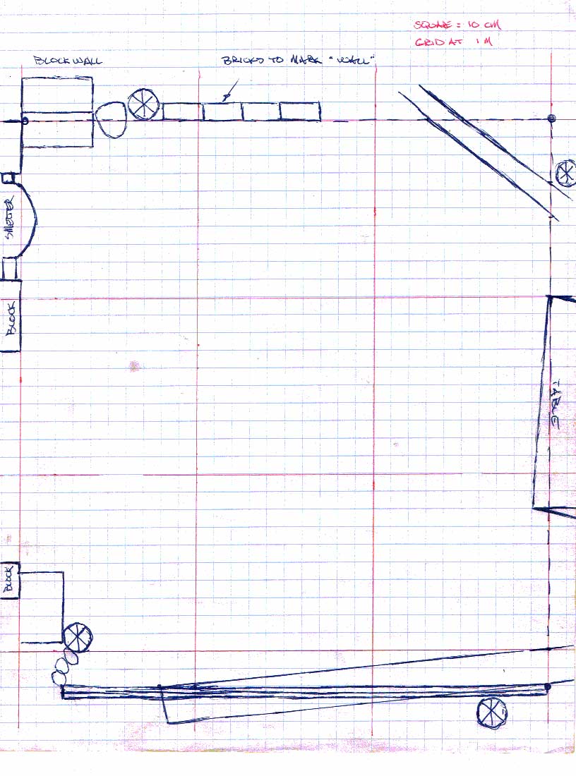
I have taken the various drawings and modified them in Photoshop to a uniform scale. I have made up a couple of overlays, so direct comparisons can easily be made between the archaeology and our proposed work area.

First : What was found is obviously the last stage of a multi stage process. It is my opinion that the layout of objects within the confines of the building appear to be positioned for final consolidation of a bloom to working bar.

Second : The actual smelting furnace (if it was sited inside the structure at all) was obviously broken up and removed. There is very limited material remaining which can be attributed to a furnace. This compounds the problem of attempting to visualize how such a smelter may have been constructed or operated.

Third : Terminology as used between the various reports and observers is creates a significant problem, both in understanding exact meanings and maintaining a consistent language.

In the primary report (Stine-Ingstad) there is little break down between the various iron smelting slags. Dr Wallace's field drawing indicates 'smelting slag' and 'indefinite slag'. (Although 'bloomery slag' is indicated on the key, none is shown on the drawing *). There is a clear distinction made between slag products related to forging, and those derived from smelting operations.

Dr Wallace told me (and also in Stine-Ingstad) that there were pieces of furnace wall found, described as 'bear' by Unglik. This is an industrial term, meaning "material resulting from the reaction of the molten slag with the refractory lining of the furnace". This is pretty straight forward, and something we are well familiar with from our own work. Although the measurement of the fragments found is given as 'ranging from 2 - 10 cm' but 'most the size of an egg' this most likely represents the fused through sintered portions of what was a thicker wall.

Dr Wallace has told me that although her original field drawing differentiated between 'clay' and 'refractory', she feels that distinction was not very accurate. The two terms arose from different language used for similar materials by herself and Uglik.

The wall material is described by Rosenquist, and later by Unglik, as being 'kaolin'. Dr Wallace had also commented that "Some of it is 'siliceous', so it may have been tempered with sand." There quite specifically is no mention of any organic materials mixed into the clay. (We know from our own work that mixtures of either straw cobb or manure have quite distinctive appearances in the furnace wall debris.)

I contacted John Walls of the Pottery Supply House (where we purchase our clays and oxides) for some technical advice:

"Relatively pure kaolins "slump" at 3200 - 3400 F [1760 - 1870 C] but deposits of clay
world wide are often mixtures of kaolinite and other minerals which can
deform at much lower temperatures. ... I think the reason that data is reported for [cone 11] has
more to do with the traditional firing temperature of porcelain and high
fired stoneware than whatever sintering may be going on.
You should be able to use a kaolin like EPK for this purpose or a ball
clay like Bell Dark (more plastic, stronger when dry but having higher
dry shrinkage), both of which are very refractory. "

The material data sheet for commercial 'EPK Kaolin' shows that material to be primarily a mix of 46 % SiO2 and 37 % Al2O3 with a sintering temperature of roughly 1350 C. Bell Dark (of which there is a supply on hand) is listed as primarily 59 % SiO2 and 27 % Al2O3, and sinters at roughly 1315 C.
To put this in perspective with the normal operations of the smelter, we have recorded readings as high as 1510 C, with normal working temperatures being closer to the 1350 C range. In our experimental series, we shifted from straight clay to clay cobb construction with number three. Although cobb is more of a refractory than straight clay, its main advantage is greater durability and resistance to cracking.

Taken together, the proposed construction material for the first reconstructed furnace is straight Bell Dark clay. Course beach sand may be added as required to stiffen the mixture. Mixtures of Bell Dark with EPK Kaolin, or straight Kaolin may be considered for later furnaces if the performance of the initial furnace suggests changes are required. Any individual furnace is only required to endure a single firing. Extra care will be required through the drying / pre heat phase due to the problems of water to steam expansion and evaporation from thick solid clay walls.


Furnace remains at Erlandsgard, Norway

A number of prototype furnaces have been suggested as the pattern for that used at LAM. These are from Norway, at Skeie, Elandsgard, Dokkfløy. All are what I have been calling a 'boxed short shaft', a clay cylinder surrounded and supported by large stones. Our own experience has shown that a clay cylinder alone will certainly withstand a single, if not several, smelting cycles. The primary reason for constructing the kind of massive structures as seen in the examples is to build furnaces intended for 'industrial' production (an extended series of firings).
On top of this, there were certainly not enough stone slabs uncovered in the excavations to encircle a full smelter.

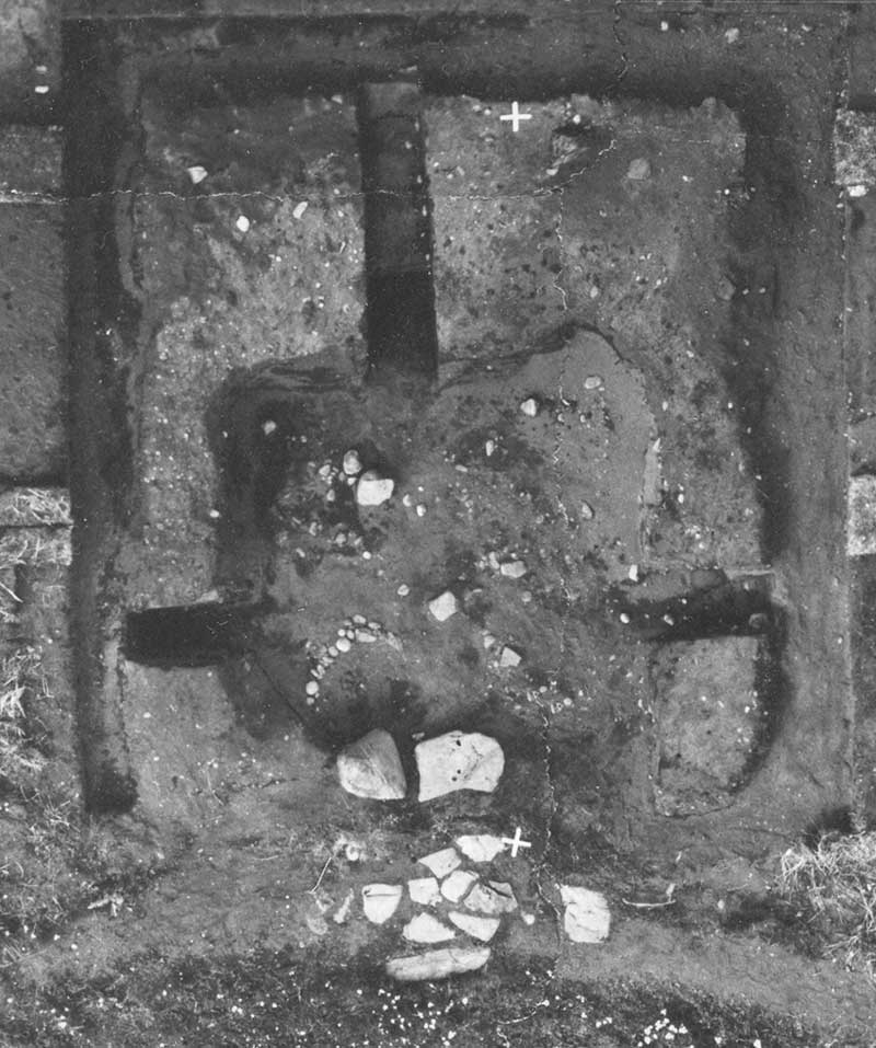
Looking at a photograph of the central deposit of charcoal, it is possible to envision a roughly circular pattern of charcoal and clay (mentally removing the 'anvil stone' and its fragments). From this a tongue of mixed charcoal and slag extends towards the open door of the structure. This is roughly the pattern created from a bottom extraction process.
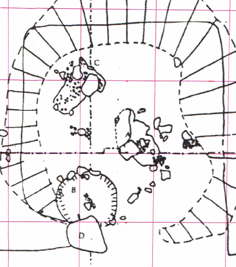
If the photograph accurately records a bowl shape depression into the underlying soil, containing charcoal and surrounded by a ring of clay, what may be seen here is the base level of a smelting furnace which has been cut away at ground level. Working with a roughly scaled image, I have superimposed circles which appear defined by the ground features.

The result is an internal diameter of 20 cm, a bit small for a Norse iron furnace, but certainly proven functional by our experiments. The advantage of this smaller furnace would be a reduction of the ideal air volumes required. Using the proven Sauder & Williams method, between 315 to 565 litres per minute is indicated, a volume more easily achieved with Norse styled bellows.
It is possible to extend the ground features to a circle marking roughly 30 cm, with perhaps a second ring at 40 cm. The 30 cm diameter would mark a wall thickness of 5 cm. This is suggested as a minimum thickness for a straight clay construction, bearing in mind that the total furnace height needs to extend at least 60 cm above the base. Most likely, the walls would be thicker at the base, tapering in towards the top. This would help account for the random thickness of the 'bear' wall fragments excavated.


* This is not intended as a criticism of the original excavation. By Dr Wallace's own admission, the entire team was completely unfamiliar with iron related debris in fine detail. It is important to note that our pieces are 'fresh', while the archaeologists are attempting to assess samples in the ground for a good 1000 years!

Norse in Northern Canada

----- Original Message -----
From: Lodin Myklebust
Sent: Wednesday, May 27, 2009
Subject: [Norsefolk_2] Second Canadian Viking Village?

Vikings in Nunavut?
Find may indicate medieval Norse presence on Baffin Island.
By Randy Boswell, Canwest News Service

One of Canada's top Arctic archeologists says the remnants of a stone-and-sod wall unearthed on southern Baffin Island may be traces of a shelter built more than 700 years ago by Norse seafarers - a stunning find that would be just the second location in the New World with evidence of a Viking-built structure.
Link to the full story in the Montreal Gazette

Tuesday, May 26, 2009

John Little - Inflating Sheet


This short sequence was filmed at last weekend's 'Great Lakes International Ironfest' in Buffalo. (May 23, 2009)
John Little is a well known and respected Canadian artisan blacksmith from near Halifax in Nova Scotia. I had met John quite briefly at CANIRON 5, where we both were feature demonstrators. Both of us were extremely busy (smelt for me, his home event) so hardly had time to shake hands at that point. John has also come into Ontario to teach at Haliburton, plus run a workshop for Ontario Artist Blacksmith's Association last fall. I was unable to make that weekend for being busy with other work. So long and short, this last weekend was the first chance I have had to see John work, hear him talk about his work - and actually visit with him.


(John working at the anvil, assisted by his wife Nancy)
The quality of the sequence is not great! Something with the lighting in the industrial space used for the event was causing the camera to cycle to dark about every 10 seconds (as you will see). For that reason I kept the clips pretty short. I also was filming from a good 10 metres away, and the hand held footage is a bit jumpy.
What you can see is the second part of a more complex element. John had worked two pieces of 16 gauge mild steel sheet. These were folded down the long axis, then the fold forged and rippled. Last the fold was opened up again, leaving an organic spine or rib down the middle of the sheet. The sheets where then cut to a rough oval, then carefully MIG welded after a length of small diameter tubing had been inserted in one end.
A tube attached to a low pressure air source was fitted, and the two steel surfaces carefully heated. (Also seen in the video clip). As the metal came up to forging temperature, John bled air into the 'balloon' to inflate it. Control of temperature, position and pressure combine to create a fully three dimensional form. Up till now, John has been cutting the finished form in half to produce a number of 'bells'. This follows his interest in forging and creating musical instruments and other 'sound sculptures'.

I was stuck by the possibilities of such contoured shapes for any number of sculptural objects - for example as the bodies of fantastical fishes or insects...

Monday, May 18, 2009

'Quenched in the body of a Slave...'

Modified from a recent posting to Norsefolk. The original conversation had started with a 'traditional' reference to using blood as a hardening medium for Bronze. I had pointed out that all the non ferrous alloys are in fact annealed (softened) through quenching. The topic had drifted, as such so often do...

Effectiveness of Blood (human or otherwise) as a quenching medium:

Last time this came up, I did some actual research, then wrote a long article on my own blog repeating the results. I refer anyone who really is interested in the details to that piece:
Applied Knowledge - Quenching
What is key here is the table near the bottom of that post, showing the effect of salt added to water changing hardening rate. Even small percentages of salt have a noticeable effect.
Blood tends to have quite consistent salt content
Hence the possibility that a bowl of blood might prove an effective quench medium.

Quench a blade in a BODY ? - Foolish!
Now, I want you to think about this:

A body (human or otherwise) is completely inconsistent in nature. It has muscle, fat, liquid pockets, air pockets, various organs with differing densities and fluid contents - even bones.
If you took a hot metal object and plunged it into a body, there would absolutely no evenness to the cooling, thus inconsistent hardness generated down the length. NOT what you want for any cutting edge!
If you took a *long* hot object (sword) and plunged it into a body, and the tip struck a bone (pretty good chance) the part of the object still hot would simply bend due to the force. Now you have a warped inconsistently hardened blade.

If you were to use a LIVE body, that body is certainly going to wriggle as the hot blade is inserted. What do you think happens to the hot (ie soft) end of the sword when you attempt this? Completely warped beyond any usefulness - plus inconsistent hardness!

If a historic smith ever was to resort to such pure theatrics, you can be sure that the 'soul stealing' blade was destined for the scrap heap.
"Here, let me clean that off in the back room" the smith tells the richly paying customer. And down from the wall comes an identical blade quenched *properly* in urine or sea water the day before...

Darrell

(one of my LEAST favourite pieces of 'fakelore' - "A little learning is a dangerous thing")

******** FAST FORWARD **********

Addition - August 2015

I had a personal e-mail sent to me by Professor Helmut Föll, recently retired from the University of Keil (Germany) :

You don't know how right you were in your analysis that quenching a sword in the body of a slave is pure BS!
I found the source of that nonsense, here it is:
 

Let me emphasize that there are no early Arabic texts. The whole thing was a kind of April 1st joke in that Berlin Newspaper in 1894. 

In his blog post, Prof. Föl discusses a number of historic receipts for quenching solutions. He provides the original texts, translations, plus interpretations of the (often hidden) meanings for the individual components.
Not too curiously, carefully manipulated urine figures prominently in many of the historic 'secrets'.

In my own return communication to him, I had mentioned my belief that the original source for the 'quenched in a living slave' concept was from an Early Medieval Arabic text. His research into historic sources has pointed to this itself being nothing more than another piece of the 'fake-lore'!

Tuesday, May 12, 2009

Jake Powning - VA Pattern Welded Sword

I met Jake at CANIRON V, in Annapolis Royal NS, back in 2005. I found Jake to be a kindred spirit. The quality of his work is exceptional, I would say his work on pattern welded blades is amongst the best of anyone working in the field today. What sets Jake's work apart is that each blade is a complete design package from forging to carved scabbard and cast mounts. Truly beautiful work, worth attempting to emulate.

Jake has also produced a beautiful web site, wonderful graphic layout with high quality images throughout. This morning I was pointed to a photo essay he has created, detailing the creation steps on the metalwork for a Composite Pattern-Welded Viking Sword:

The direct link to the full article : Go HERE
(Please go take a look, then come back)


This is the completed sword. The blade is composed of two, 7 layer twisted core rods, with a 12 layer edge wrap. As with all Jake's work, cast bronze furniture and matching carvings on both hilt and scabbard finish the work.

I wanted to point out a couple of things from the working sequence:

You see the two prepared core rods in this image, ready to be stacked and welded to make the full billet for the blade. Jake has welded a flat stack at 7 layers. I normally start at 9. Note to those who think this is mystic! To effectively weld the starting block, you ideally want a pile as high as it is wide, and roughly 4 - 5 inches long. The length is what you can effectively weld in one heat. Balancing the width and thickness means you get uniform heat penetration - thus a solid weld. Turns out that (depending on plate thickness) this starting stack will be from 7 to 11 pieces, with 7 to 9 being most common on the artifact blades. Believe its 'lucky seven' or 'nine for O∂in' if you want...
But the real point: Jake has twisted his core rods as squares. I personally have taken to running a fast set of hammer stokes down the edges of the twisted rods to convert them is rough octagons. I find this makes for less problem with tearing the corners during the tight twisting. Also I find this method is less likely to result in diamond shape voids in the welded billet (spaces from the overlap of the twist).
I mention this, but Jake's results speak for his control of his technique!


I wanted to include this image here, as it is quite interesting. Jake has forged the edge wrap as a single piece, and fitted all the pieces together. These are being held in place with a forged and fitted heavy metal collar. In the image, he has made at least two of the series of 'travelling welds' down from the tip of the billet that join the four pieces together. You can clearly see the borax flux 'downstream' from the last weld location. That the metal remains so clean suggests the use of a gas forge (Dark Side of the Forge!). There is amazingly little compression or distortion of the welded areas, which makes me think that Jake may be using the hydrolic press he mentions for the weld (or maybe he is just a heck of a lot more precise than I am!).
Again, you can only effectively weld at best 6 inches of material in a single heat cycle. As Jake runs the travelling weld series down from the tip, he will tap the collar forward. (Scott Langton used this collar method on his reproduction of the Sutton Hoo sword.)

Thanks to Jake for publishing such a clear description of the creation of a pattern welded sword. Would be sword makers are advised to study the article closely, there is a LOT of good information there.
(Images are Jake's, loading direct from his web site.)

Friday, May 08, 2009

HEAVY Forging!


This clip shows the ongoing work for the Reade / Maxwell House project. Part the the assemblage are two structural support beams. Each is roughly nine feet long, made of 3 1/2 by 3/16 side wall square tube. In place these will hold up the open edge of the first floor, where it is cut away to expose the stairs down to the basement - and a wide bank of windows. Rather than use standard round jack posts, I am forging a long groove into each of the flat sides of the tube.

As you see in the video, I am using a cross peen hammer as a top fuller tool. Hammering is done with a four pound hand sledge, as heavy a hammer as I ever work with. Even still, the forging progresses in roughly 16 inch long segments. This is about as long a length as I can bring to temperature in my three burner architectural gas forge. I had designed this forge so that it can be opened up along the front wall, permitting just the kind of work that you see. Each beam weighs something in the range of 80 lbs. Fortunately, last year I had invested in a heavy layout table. The top is a single piece of 3/8 thick steel, 4 x 8 feet. This allows me to forge the beam on the table surface (rather than trying to haul it, while hot!, over to an anvil).

You will notice I am wearing a glove on my left hand. Even with the circular metal shield fitted over the handle, my hand is uncomfortably hot after a forging sequence, even through the glove. In fact my right hand gets too hot, just from the limited time my fist is close to the beam while striking it as seen. The amount of radiant heat off the beam is incredible!

Thursday, May 07, 2009

A Weekend Course - 'What will I get out of it?'

... I am interested in your Blacksmith courses. What I am looking for is a business I can start that involves working with my hands and making everyday items. ... I know a blacksmith will be a life long learning process but what I would like to know is how long will it take me to make simple items I could sell at local markets (pot holders, wine bottle stands, plant hangers, etc.)? Is this a realistic goal? If I took your basic course how much additional practice would I need to produce items with consistent curves, quality etc.? ...


Once again - this article is edited from my response to the question. With the current economic trend, I have been getting an increase in this type of inquiry.

1) Estimated start up Investment - minimum $1200 (of course you may have some of this stuff)

Anvil - $ 300 plus : That assumes you can *find* an anvil, and you get a reasonable price on it. You need at least 150 lbs for any serious work, and figure about $2 per lb is typical in Ontario right now.

Forge - $350 : That's for a professional level cast iron fire pot, brand new (John Newman), and assumes you make up the actual table itself, and use an electric blower. If you use one of the shallow dish forges, those run (Ontario) anything from $100 through to maybe $200 (that's will a small blower). Note that dish forges are not for serious, sustained work. At the bottom end, a brake drum and pipe forge could be cobbled together for maybe $30. A small commercial gas forge runs closer to $450. (Check those sold by David Robertson)

Post Vice - $75 : A lot of variation on price here, assume a smaller 4 inch in reasonable shape.

Drill Press - $250 : a small bench top from some place like Busy Bee

Bench Grinder - $50 : also from cut rate tool supplier

Selection of hand tools - $100 : This assumes low quality, gives you a couple of hammers, pliers, hacksaw, few punches...

Sundry - $100 : Largely expendables, things like coal (Robb Martin), drill bits, sand paper, safety glasses...

Of course, this is just for a simple, almost hobby level set up. To work at a small business level, a suitable vehicle (van or pickup) will be required. A complete sales booth set up with storage containers. Considerably more investment in power tools (band saw, sander, torches, welder). Also the physical workshop itself, which might include a purpose built construction.

2) Time to Target - variable!

Each individual will develop hand skills at wildly differing rates.
An example: I am finding the typical student these days will take anything from 45 to 90 minutes (sometimes more!) to make their first pair of 'S' hooks. Now, when I am on form, I can do the same in roughly five minutes (that's three heats each). Why? I've done it a thousand times!
So the real truth is that you will have the raw knowledge on how to make any number of the individual *shapes* that combine to make simple objects after a weekend Introduction to Blacksmithing Course. The course will certainly not cover all the possible combination of those basic shapes into objects. Most importantly, being able to make some object, and to be able to make it consistent enough and *fast* enough for economically viable production are two entirely different things. That speed and ease will only come through practise and repetition, at a rate that will vary by individual.

3) Goals - "You can have it FAST, you can have it CHEAP, you can have it GOOD. But only ONE of those!"

You can speed your time from first training to viable production by using a number of short cuts: Simple designs requiring limited elements. Cold forming methods in place of hot forge work. Extensive use of jigs and dies.
However, speed gained at the starting end will be skill limitations in the long run. If you make up jigs for all your standard shapes, that will quickly allow you to crank out those standard shapes. You will at the same time seriously limit your ability to progress past the most basic types of objects, and even your simple pieces will have a very mechanical look.
For that reason, in my programs I stress the use of hand forming over the anvil. It makes work harder and slower *at first*. In the end however, skills will develop which allow you to be able to create any form you can imagine.

4) Meat on a *good* weekend Course

A well balanced weekend 'Basic' program, taught by a skilled (and experienced) teacher should give you almost more information than you can absorb. There should be a large amount of practical working time, under close supervision (ie - low student to teacher ratio). There also should be considerable background and theoretical discussion on tools, safety, working methods, applications. I expect my students to acquire enough raw information that it will take several months of practise to refine the skills taught.

A comparison : Students will learn as much in the 18 hours of my own Introduction to Blacksmithing course as I was able to figure out in the first 18 *months* of working on my own.

Other articles you really should read:
'Will you take an Apprentice?'
'A Career as an Artist Blacksmith'

I also refer readers to the details available on my own Courses on Blacksmithing and
Educational DVD

Tuesday, May 05, 2009

L'Anse aux Meadows Smelt - Working Area

One of the specific challenges in the recreation smelt for L'Anse aux Meadows NHSC is working inside the same physical set up that is suggested by the archaeology:


Overhead photo from 1974 excavationScaled drawing (1 meter grid)


The photograph and illustration above were kindly provided to me by Dr. Birgitta Wallace.

In the photo, the arrangement of flat stones seen in the lower centre are not part of the artifact set. Those stones were placed to protect the archaeological layer by Ingstad & Stine at the close of their original excavations in the 1960's. The largest stone in that area (lower grouping, but upper left) is in fact part of the artifacts.
The illustration to the right has been slightly enlarged (to match my workspace drawing below) and I have added the 1 metre grid to it.


This is a drawing of the current smelt working area here at Wareham, with a scale matching the archaeological drawing above.

You can see that the overall size of building J (what is described as 'the furnace hut' or 'the smithy' in the original reports) is roughly 3 x 3 metres. The exact measurements in Dr Wallace's 1974 report is a width of 290 cm and length of 320 cm. As you can see, we can closely match those measurements under the overhead of our current work area.

In the next posting, I will start talking about just what the archaeology may (or may NOT) tell us about what happened at Vinland about 1000 AD.

Monday, May 04, 2009

L'Anse aux Meadows Smelt - Ore Analog

A proposed mix for the DARC Dirt 2 - LAM analog:

A current project now in its initial stages is DARC working towards a possible full scale interpretive presentation at L'Anse aux Meadows NHSC in summer of 2010. July of that year marks the 50th anniversary of the archaeological site by Ingstad and Stine. Part of the presentation by DARC will include an iron smelt, replicating the one undertaken by Leif Eirikson's crew some time about 1000 AD (the first iron production in North America).

Readers can expect to see a number of commentaries and reports on this specific experimental series as the work progresses from the theoretical to the practical.

There are a number of elements that will frame the reconstruction smelt:

- Work inside the confines of the 'Furnace Hut' structure found at LAM. (a roughly 3 x 3 metre space, roofed and open one side )
- Furnace construction of free standing stone slabs.
- Air provided by human powered double bag bellows type.
- Ore used is local primary bog iron ore
- Determination of tuyere type and layout (unknown)
- (on site production of charcoal as related demonstration / project)
- (on site use of stone surface for consolidation process)

The core of the smelt process revolves around the ore. If you have been following the many notes related to experimental iron smelting, you have seen how historically it was primarily the ore that determined the location of the iron smelting. Ore also shapes the dynamics of individual furnaces.

The largest element of the Norse decision to attempt to smelt iron at Vinland around 1000 AD is the ore itself. When the boat crews cut and pulled up the peat blocks to build their over wintering houses, they would have exposed a large quantity of primary bog ore. Now, there are some differences of opinion of just why Leif's crew undertook an iron smelt, but the important fact is that they in fact did.

I had been provided with a small amount of the ore off the archaeological layer, as uncovered by Dr. Birgitta Wallace during excavations in the early 1970's. Of course there are a number of potential problems attempting to match this sample to what might have actually been available (even at exactly the same spot) 1000 years ago. As the formation of primary bog ore is a chemical process with a very large organic component, a change in physical environment could also change the material. More important for this specific series, we certainly will not use actual bog ore for the many tests. (There is a very good chance that even for the on site demonstration this may not be possible. Parks Canada does maintain a very strict 'no environmental impact' policy on all of its sites.)

The original LAM ore sample provided by Birgitta (tested by R. Hansen for Arne Espelund) shows:

Fe2O3 - 89.5
( Fe - 62 )
SiO2 - 1.24
Al2O3 - 2.45
MnO - 5.33

One of my largest concerns right now is about silica content - the components that make the slag bath. Arne had commented back then (and I totally agree) that the archaeological sample was lacking in silica - and would make for a 'dry' smelt. The silica / slag is important for controlling the final carbon content of the metal. Too little slag, and there is a good chance the metal will absorb way too much carbon, resulting in a cast iron material (which can not be forged). Our past experience is with clay structures, which at smelting temperatures melt to create a surplus of slag (if anything). The rock available in Ontario is not a perfect match for the basalt type stone in north Newfoundland. (Even at that, that source stone has to be gathered up off the Canadian Shield, considerably North from Wareham!) The temperatures inside a working smelter are high enough to melt even basalt, but the rate of melting on Ontario types, thus slag creation from the stone, may both vary and be important.

The obvious solution to the problem of available ore materials is to turn to an analog. This is in fact something we have already worked considerably on, building on Robert Gissing's early work on DARC Dirt. I have also been trying to pull together reports and data detailing the chemical components of the various ore types that have been used in past smelts. Comparing it with some of our other successful ore / smelt combinations, it looks like we have got the best results with a silica contribution from the ore of something in the range of 5 plus %, with the combined SiO2 and Al2O3 at roughly 8 %.

Utilizing a 'Black Iron Oxide' from the pottery supply:

Fe3O4 - 93
( Fe - 67.3 )
SiO2 - 3.5
Al2O3 - 3.5
MnO - 0.0

Using that as a base, and if we disregard the 10 % flour mixed in as a binder (as it will cook off anyway and does not effect the iron chemistry), I'm suggesting we add 5 % silica to make for a bit more 'juice. That would leave us with something :

Fe3O4 - 84.4
( Fe - 64.1 )
SiO2 - 8.8
Al2O3 - 3.3
MnO - 0.0

When we mix, the ratio would be 10 % flour, 85 % black oxide, 5 % silica - not counting the water weight. Past experience has shown that a good 8 kg or so of ore is required to establish a working slag bowl inside the type of iron smelting furnace that will be used here. The target yield will be roughly 3kg (plus) as that is the estimate of what was produced originally. With a fairly normal yield expected at approximately 25 - 30%, a minimum of 15 plus kg of ore analog will be required for each full test smelt.

Take a look at a table showing the major components of past ore types
 

February 15 - May 15, 2012 : Supported by a Crafts Projects - Creation and Development Grant

COPYRIGHT NOTICE - All posted text and images @ Darrell Markewitz.
No duplication, in whole or in part, is permitted without the author's expressed written permission.
For a detailed copyright statement : go HERE