(This is the first part of a commentary I have been working on for the Ontario Artist Blacksmith Association web site.)
A well known comment in popular culture is "You talk the Talk - but can you walk the Walk".
Terminology, what you say about what you do - and just what you mean by it, is extremely important. 'Saying what you mean and meaning what you say' is one measure of someone knowledgeable in their trade. This is even more true for any artisan involved in a traditional skill in a modern world. The blacksmith also faces the twin problems of being involved in a highly technical and mysterious process which has also been surrounded by huge public misconceptions.
We all know how retail stores and mere fabricators deliberately and knowingly misuse the technical language of the blacksmith to increase the value of their products in the eyes of the customer. Its also painful to admit that within the blacksmithing community itself there are those who have converted what were once technical terms into mere advertising copy. Unfortunately, this relatively recent trend has also been increasing in frequency. "Its just easier to tell them what they want to hear" is an explanation that is often given.
To that end, some terms should be defined, with some of the related history of their use (and misuse!) given.
Artist:
There may be as many definitions of the term 'art' as there are people who are involved in the creation of it - hence 'artists'. One useful way of considering an individual object : If the function of the object is primary concern to the piece, it could be considered to be 'craft'. If the appearance been the major factor of the overall design, it could be considered to be 'art'. Needless to say, there is can be considerable overlap between the two aspects - what is useful can be beautiful and what has beauty can be functional. At its core however, the artist is most concerned with the overall design of each object, to maximize its decorative qualities beyond mere technical constraints.
Ideally, the 'artisan' will be one who blends form with function, employing skill to create distinctive objects that are interesting to the eye while at the same time being a pleasure to use and of high quality.
Blacksmith:
Quite literally 'iron worker'. 'Smith' is derived from a Germanic root - 'smyte', meaning to strike. Historically, smith has referred to those who work metals employing hammers. Iron has been known as the 'black metal' since ancient times. This is a reference to the dark grey oxide that forms on an iron surface when it is heated to incandescent temperatures. So to truly earn the description as 'blacksmith' you must work iron metals at glowing temperatures using hammers.
Hand Forged:
The forge is the fire used by a blacksmith to heat the metal. So 'forged' refers to metal which has been heated and then shaped while it is hot. (It should be noted that jewelers use 'forged' to refer to any metal that has been hammered, in their work primarily cold. As the term originally derives from the work of the blacksmith, this usage is incorrect.) 'Hand' means just that - work that is undertaken with hand tools. A modern alternative would be industrial 'drop forged' where all the hot forming work is done with mechanical tools.
(to be continued)
Thursday, June 29, 2006
Friday, June 23, 2006
'What they Carried' - On Norse Tents
(This altered from a post to NORSEFOLK - arising out of a discussion of possible Viking Age tent designs)
As re-enactors of the Viking Age, our challenge is always balancing our modern requirements against what is known historically.
We make our assumptions on what comprises personal equipment carried in the Viking Age (entire range from skin out) largely from burials and garbage. Nether provides a truly accurate picture. On top of this are the twin problems of survivability and random discovery. (see also 'Aunt Martha's and Damthings')
Much stress is placed on burials - but there is a largely symbolic nature to anything that goes into a burial. People tend to get buried in their best or favorite clothes and accessories. This is unlikely to be ALL their clothes. Same goes for the tools included, these are 'some of' only the major types that defined the person. When you work yourself in that same craft - you see how what was included is often missing critical pieces. Classic examples that are missing are looms for weavers and bellows for blacksmiths. Another consideration is the distinction between what would have been considered 'personal' as opposed to 'collective' equipment. Is a cooking pot actually personal gear - or something that belongs to the family itself? What is placed in a burial will also be balanced against necessity of the survivors. If there is only one axe in the family, its pretty unlikely that it will be buried. The Norse were nothing if not practical, and ensuring the continued survival of the living is sure to take priority over providing for the requirements of the dead.
My own opinion of the World of the Norse is that there would have been far more objects held as 'group ownership' than what we consider as such in our modern world. We constantly under value the 'cost' of objects with our modern (especially N. American) buying habits.
An example of all this would be a fire steel (strike-a-light), which from its lack of frequency in Norse finds and the relative complexity of the objects themselves certainly suggests a 'one per family', presentation object. Know know from my own work that these would be 'expensive' objects in terms of the skilled labour required to create them (from dirt). Not something that every person has on their belt.
The other side of this as re-enactors is how we both wish to provide for ourselves as individuals in a detailed environment. This gets magnified by our attempts to create public presentations (even if only for other re-enactors). Our modern pence of privacy and requirement for comfort leads us to all over equip ourselves. Our ability to easily transport both raw materials and finished objects also leads us to accumulate huge equipment loads.
The easy solution to tents is to do exactly what the Norse did. One tent, created by lashed poles and sail cloth - but shared between the entire crew. Six feet by two feet per person.
I find that so much of the discussion on tents is almost always centred around the very modern problems of how to pay for the pieces and then transport them. An Anglo Saxon (wrong time period) geteld is often mentioned as a purely modern solution - primarily because of the ease of transporting the poles. The design is not Scandinavian or from the Viking Age - and carrying poles is not a historic problem when you are always traveling by ship. Consider that you are exchanging the insignificant cost of the wood poles of and A frame (in the Viking Age) for the huge cost of a specially cut and stitched fabric cover (against the VA use of the existing sail). I expect the weavers to support me on this.(What were the woman hours required for a sail? Now spend MORE than that for what is a single use object?)
for a look at a chieftain's tent
for a look at a bondi's tent
So - the fast way to get a cheap A frame cover:
Go to a good hardware or paint store. Purchase canvas painters drop cloths. These will be unbleached cotton canvas rough stitched into typically 8 x 10 or 10 x 12 sheets. I have not purchased this recently, but 10 years ago the cost each sheet was about $40 CDN. Two sown down one side makes a rectangular 'sail' tent cover. Get one more and cut into one large triangle and two smaller ones to make the back and two front flaps for a fitted cover. That gives you a minimum of 8 x 8 interior tent about 7 feet at the ridge - for a days work and about $100 US. You will want to SOAK the lighter canvas in Thompsons Water Seal - the water based version.
There are plans for this tent on the Encampment web site (under 'Creating the Artifacts') Frame
Cover
As I live in the country - getting the poles for an A frame is trivial. I have used 'barn pine' - rough cut 1 x 12 lumber for the end boards. ripped down on the table saw to 6" wide. I have used a sapling for the ridge pole. I'd suggest making some kind of a deal with those re-enactors you know who are rural to cut a sapling in trade for something.
For those who cry the space in their car problem. I have also made a smaller (8 x 8 by 6 ft tall) tent out of standard 1 x 4 lumber. I joined two shorter sections between two metal plates with bolts for each of the boards.Cost about $50 for the frame.
The whole thing fit in the back of a Honda Civic hatchback.
Thursday, June 15, 2006
Ring Pins...
 Ring Pin (David Robertson) and Antler Comb (Dave Cox) at LAM
" ... A few questions came up during last weekend's display which I could not answer. ... Is it certain that the ring pin was used as cloak pin? Some of the handyman visitors to my display speculated that it was in fact a plumb bob, used for setting poles or ship masts straight. This is an interesting idea, and I experimented. The narrowed area just below the ring is perfect for wrapping string into, and when the pin is hung by the ring at the end of a string, the swiveling ring helps dampen the ring's pendulum swing. In construction projects using tall poles or in setting ship masts which were frequently lowered and raised, a plumb bob would be very useful to make sure the object was set vertically. And it's just the kind of thing to be forgotten on the ground at a construction site, or buried with the mariner who used it, to be found a millenium later by the archaeologists. If it's a cloak pin, why does a cloak pin need a swiveling ring on the top, but nothing to keep the heavy blanket sections it is holding tiogether from simply sliding apart along the pin? The contemporaneous twisting ring-brooch style cloak pins from viking and celtic sites have a locking method to prevent this from happening. ... "
Dave Nordin
Your description is workable - but is a possible secondary use. Ring pins are common in both Iceland and Norse Ireland bracketing 1000 AD. In burials they are found either at the centre chest (women) or on the right hip or right top shoulder (men). Pretty obvious.
In this use, take a smaller gather of cloth. This should fit along the cylinder part of the pin. There is then a bit of a 'stop' at the slightly wider square pin. Also, if you take a length of wool and attach it to the ring end, you can wrap this cord around the pinch of cloth once in place. This pretty much locks the ring pin in place. (Does that make sense??)
 Although there may be a requirement for that degree of accuracy (the suggestion as a plump bob) in ship construction, it certainly would not be required for house building! The buildings at LAM - or Greenland or Iceland for that matter, use a simple timber frame to support the turf blocks that insulate the roof. The walls are piles of turf blocks - each roughly a half metre by on metre and about 15 cm thick. The wood is all cut straight from log, so all the elements are tapered and irregular to begin with. Anything placed straight by eye would be more that square enough!
Interior of reconstructed Long House at LAM.
Monday, June 12, 2006
June 10 Smelt Draft Report
Experimental Smelt 16/D8
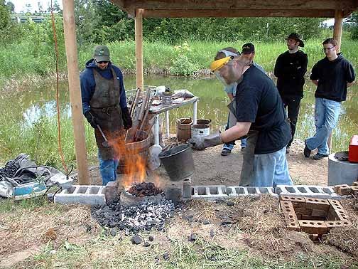
This is a fast overview of the conduct of the smelt undertaken on June 10 at Wareham. The iron masters were Kevin Jarbeau and Dave Cox, with primary assistant Ken Cook. Darrell Markewitz provided some technical advice (but an attempt was made to keep me out of it!). General background labour by other members of DARC.
The event was open by invitation to a select group of observers. Some members of the wider blacksmithing and the early period re-enacting community joined DARC for the day. We were also fortunate enough to have a couple of academic researchers present.
The smelter was of the general form of the 'Norse Short Shaft' type. This is a form of smelter that the group has past experience with. In this case the smelter has been constructed in a 'half banked' arrangement. The new smelting area features a short earth bank re-enforced with concrete blocks about 60 cm high. A hole was cut into the bank, roughly 45 cm in diameter and tapering slightly towards its base. The smelter was set into this bank, with its mid line at the line of the bank.
The smelter itself was constructed from clay cobb, a mix with dried wild grasses pulled off the yard. A powered commercial ball clay was used. As with past smelters, the cobb was compacted between two metal forms to speed construction. This all resulted in a cylinder about 25 cm internal diameter, 65 cm tall, with walls roughly 7.5 cm thick.
The smelter was constructed on May 30. The metal forms remained in place for about two days, and then were removed. (The paper seen serves as a separator to keep clay sticking to the metal.) At this point the gaps at the front edge of the smelter and block wall were filled with bricks. The space between the smelter and earth was filled with a mix of ash, sand, and burned charcoal and slag from an earlier smelt. This was then covered with a mesh feed bag to air dry.
In the two weeks till smelt day, the smelter settled under its weight down into the lightly compacted earth. This moved the floor of the smelter down about 5 cm. Some slumping at the base and thickening of the walls at the base as well - although both effects were minimal. Although the upper areas of the cobb were fairly hard and dry, the base areas were still quite damp and plastic.
The day before smelting, the tuyere was mounted and tap arch cut. The tuyere was set about 45 cm down from the top of the smelter, at the standard 22.5 degree down angle. The tip of extended in 5 cm beyond the smelter interior wall. The tap arch was located at the base as close to 90 degrees offset from the tuyere as was possible, roughly 20 cm wide by 13 cm tall.
At this point a wood splint fire was started, and allowed to burn for several hours. Eventually a heavy dished metal plate was put over the top opening to allow the coals to bake the structure overnight.
On the next day, the base of the smelter was determined and positioned with charcoal fines, roughly to the top of the tap arch (about 7 cm below the centre of the tuyere tip). preheat with wood was started about 9 am, switching to rough charcoal after 70 minutes (marking the official start time). Graded fuel started at plus 40 minutes. Air was supplied via the standard vacuum blower used in the past at about 700 litres per minute. The first ore charge was added at about plus 1 hour 15 minutes. The ore used was the Virginia rock ore (thanks to Sauder & Williams at about 65 iron oxide).
As with past smelts, constant time intervals were used to judge consumption and thus determine amounts of ore to add. A standard 2.2 kg / 5 lb bucket of charcoal was added at intervals ranging from 8 to 12 minutes, most at the 8 - 9 minute marks. The smelter proved very predictable in this rate. Ore was added using standard scoops (measured at 410 gm, but in practice closer to 370 gm).
In the past a smelter would 'take off', increasing consumption after the addition of roughly 3 - 5 kg of ore. In this firing, this DID NOT happen. The consumption remained constant at one bucket plus one ore charge every 8 - 10 minutes for an extended period of time. At plus 6 hours, single ore charges were still being made. At this point it was decided to increase ore charges regardless of consumption rate, and starting at plus 6 hours 20 minutes. There were some gromps on hand from the October 2005 smelt, these were added in roughly 300 gm handfuls starting at about plus 7 hours.
At plus 7 hours 20 minutes the existing charges were allowed to settle to tuyere level. Two charcoal buckets and 10 minutes latter a shock charge of about 1 kg (three scoops) was added. Again this was allowed to settle, with the last charcoal added at plus 7 hours 50 minutes.
The burn down phase lowered the burning charcoal to about half the smelter height. Starting at about plus 7 hours 55 minutes, the air was reduced and the remaining charcoal was scooped out to the top of the tuyere. The mass was then compacted / loosened by use of the Thumper. Any large masses were separated from the smelter walls and extracted from the top using Bloom Tongs. The tap arch was then opened and material was raked from the bottom to clear the smelter interior.
Meanwhile, the group of blacksmiths under the leadership of Lloyd Johnson had constructed a simple ground pit forge to one side of the smelting area. This had a brick lining and a length of 2.5 cm ID pipe as the tuyere. Air was supplied by a hand cranked blower. Fuel was a combination of rough charcoal, bituminous coal and metallurgical coke. A hard wood stubb set to normal forging height (about 90 cm). As it turned out, this equipment was not going to be required.
When the smelter was opened, the hoped for bloom was not in evidence. The majority of the ore had been converted to cast iron. This material had solidified to a plate attached to the bottom of the slag mass, but also had formed a liquid pool below, burning down into the charcoal fines base. This liquid flowed out when the tap arch was opened. The slag mass itself was mainly attached to the smelter wall across from the tuyere. Below the tuyere were two smaller iron masses, each about fist sized. These are relatively porous forgeable iron blooms.
Total duration of smelt - 8 hours 10 minutes (not including preheat of 1 hour 30 minutes)
Total charcoal consumed - about 100 KG (plus preheat, forge)
Total ore added - about 18 KG
Yield - iron blooms - 1550 gm (as two fragments)
- cast iron - 1.3 KG (one larger piece plus small fragments)
- about 1.5 KG magnet fragments of partially sintered material gathered from smelter interior with a magnet.
- there was also considerable partially sintered ore remaining adhered to the smelter interior walls (unknown total)
There was some disappointment that our objective was not reached - to produce a historic sized bloom in the range of 5 - 8 kg. In retrospect, the long delay before adding larger sized charges to the smelter is most likely the reason for the production of so much cast iron material. With only a single charge added at a time, there would have been ample reaction of available carbon in the smelter column to create the carbon rich cast material.We think that this would have been the main product during the long drawn out middle action of the smelter. The smaller workable blooms are likely the result of the final decision to increase charge amounts latter in the smelt.
Regardless, the general operation of the smelter remains successful. Iron ore was certainly converted to metallic iron. Some more experience and confidence on the part of the iron masters would have led to an earlier modification of the amount of ore added. This in turn would certainly have increased the size of the bloom produced.
No compacting of the bloom fragments has been undertaken at this point. Expect a final report on what is discovered as the blooms are worked. Details of the experiment sequence and a photographic record will be available soon on the DARC web site.
This is a fast overview of the conduct of the smelt undertaken on June 10 at Wareham. The iron masters were Kevin Jarbeau and Dave Cox, with primary assistant Ken Cook. Darrell Markewitz provided some technical advice (but an attempt was made to keep me out of it!). General background labour by other members of DARC.
The event was open by invitation to a select group of observers. Some members of the wider blacksmithing and the early period re-enacting community joined DARC for the day. We were also fortunate enough to have a couple of academic researchers present.
The smelter was of the general form of the 'Norse Short Shaft' type. This is a form of smelter that the group has past experience with. In this case the smelter has been constructed in a 'half banked' arrangement. The new smelting area features a short earth bank re-enforced with concrete blocks about 60 cm high. A hole was cut into the bank, roughly 45 cm in diameter and tapering slightly towards its base. The smelter was set into this bank, with its mid line at the line of the bank.

The smelter itself was constructed from clay cobb, a mix with dried wild grasses pulled off the yard. A powered commercial ball clay was used. As with past smelters, the cobb was compacted between two metal forms to speed construction. This all resulted in a cylinder about 25 cm internal diameter, 65 cm tall, with walls roughly 7.5 cm thick.
The smelter was constructed on May 30. The metal forms remained in place for about two days, and then were removed. (The paper seen serves as a separator to keep clay sticking to the metal.) At this point the gaps at the front edge of the smelter and block wall were filled with bricks. The space between the smelter and earth was filled with a mix of ash, sand, and burned charcoal and slag from an earlier smelt. This was then covered with a mesh feed bag to air dry.
In the two weeks till smelt day, the smelter settled under its weight down into the lightly compacted earth. This moved the floor of the smelter down about 5 cm. Some slumping at the base and thickening of the walls at the base as well - although both effects were minimal. Although the upper areas of the cobb were fairly hard and dry, the base areas were still quite damp and plastic.
The day before smelting, the tuyere was mounted and tap arch cut. The tuyere was set about 45 cm down from the top of the smelter, at the standard 22.5 degree down angle. The tip of extended in 5 cm beyond the smelter interior wall. The tap arch was located at the base as close to 90 degrees offset from the tuyere as was possible, roughly 20 cm wide by 13 cm tall.
At this point a wood splint fire was started, and allowed to burn for several hours. Eventually a heavy dished metal plate was put over the top opening to allow the coals to bake the structure overnight.
On the next day, the base of the smelter was determined and positioned with charcoal fines, roughly to the top of the tap arch (about 7 cm below the centre of the tuyere tip). preheat with wood was started about 9 am, switching to rough charcoal after 70 minutes (marking the official start time). Graded fuel started at plus 40 minutes. Air was supplied via the standard vacuum blower used in the past at about 700 litres per minute. The first ore charge was added at about plus 1 hour 15 minutes. The ore used was the Virginia rock ore (thanks to Sauder & Williams at about 65 iron oxide).
As with past smelts, constant time intervals were used to judge consumption and thus determine amounts of ore to add. A standard 2.2 kg / 5 lb bucket of charcoal was added at intervals ranging from 8 to 12 minutes, most at the 8 - 9 minute marks. The smelter proved very predictable in this rate. Ore was added using standard scoops (measured at 410 gm, but in practice closer to 370 gm).
In the past a smelter would 'take off', increasing consumption after the addition of roughly 3 - 5 kg of ore. In this firing, this DID NOT happen. The consumption remained constant at one bucket plus one ore charge every 8 - 10 minutes for an extended period of time. At plus 6 hours, single ore charges were still being made. At this point it was decided to increase ore charges regardless of consumption rate, and starting at plus 6 hours 20 minutes. There were some gromps on hand from the October 2005 smelt, these were added in roughly 300 gm handfuls starting at about plus 7 hours.
At plus 7 hours 20 minutes the existing charges were allowed to settle to tuyere level. Two charcoal buckets and 10 minutes latter a shock charge of about 1 kg (three scoops) was added. Again this was allowed to settle, with the last charcoal added at plus 7 hours 50 minutes.
The burn down phase lowered the burning charcoal to about half the smelter height. Starting at about plus 7 hours 55 minutes, the air was reduced and the remaining charcoal was scooped out to the top of the tuyere. The mass was then compacted / loosened by use of the Thumper. Any large masses were separated from the smelter walls and extracted from the top using Bloom Tongs. The tap arch was then opened and material was raked from the bottom to clear the smelter interior.
Meanwhile, the group of blacksmiths under the leadership of Lloyd Johnson had constructed a simple ground pit forge to one side of the smelting area. This had a brick lining and a length of 2.5 cm ID pipe as the tuyere. Air was supplied by a hand cranked blower. Fuel was a combination of rough charcoal, bituminous coal and metallurgical coke. A hard wood stubb set to normal forging height (about 90 cm). As it turned out, this equipment was not going to be required.
When the smelter was opened, the hoped for bloom was not in evidence. The majority of the ore had been converted to cast iron. This material had solidified to a plate attached to the bottom of the slag mass, but also had formed a liquid pool below, burning down into the charcoal fines base. This liquid flowed out when the tap arch was opened. The slag mass itself was mainly attached to the smelter wall across from the tuyere. Below the tuyere were two smaller iron masses, each about fist sized. These are relatively porous forgeable iron blooms.
Total duration of smelt - 8 hours 10 minutes (not including preheat of 1 hour 30 minutes)
Total charcoal consumed - about 100 KG (plus preheat, forge)
Total ore added - about 18 KG
Yield - iron blooms - 1550 gm (as two fragments)
- cast iron - 1.3 KG (one larger piece plus small fragments)
- about 1.5 KG magnet fragments of partially sintered material gathered from smelter interior with a magnet.
- there was also considerable partially sintered ore remaining adhered to the smelter interior walls (unknown total)
There was some disappointment that our objective was not reached - to produce a historic sized bloom in the range of 5 - 8 kg. In retrospect, the long delay before adding larger sized charges to the smelter is most likely the reason for the production of so much cast iron material. With only a single charge added at a time, there would have been ample reaction of available carbon in the smelter column to create the carbon rich cast material.We think that this would have been the main product during the long drawn out middle action of the smelter. The smaller workable blooms are likely the result of the final decision to increase charge amounts latter in the smelt.
Regardless, the general operation of the smelter remains successful. Iron ore was certainly converted to metallic iron. Some more experience and confidence on the part of the iron masters would have led to an earlier modification of the amount of ore added. This in turn would certainly have increased the size of the bloom produced.
No compacting of the bloom fragments has been undertaken at this point. Expect a final report on what is discovered as the blooms are worked. Details of the experiment sequence and a photographic record will be available soon on the DARC web site.
Friday, June 09, 2006
June 10 Iron Smelt
Sorry for not getting my normal 2 - 3 per week articles up for this week.
Saturday is the first DARC experimental iron smelt for this year. Kind of a big operation, and more so for this one as I have invited a number of researchers from Ontario universities and museums, plus a some interested blacksmiths and other Early Medieval re-enactors up to observe.
Karen from DARC is organizing a Viking Age camp as a parallel event. This will not be up to presentation standards, as its been a while since the tents got set up. This will be an equipment shake down as much as anything else. I think her and Vandy have some textile work planned, as well as some campfire cooking.
At this point, early Friday morning, I'm a bit concerned about the weather. The forecast is for 30 - 40 % chance of rain and scattered clouds today. Not likely as is coming down light but constant right now - with a solid low deck of dark cloud. My pioneer sense tells me this means a long day of constant showers. Saturday is supposed to be scattered cloud but mainly sunny. The best news is the temperatures, which are predicted to be in the high teens. A bit cool for this time of year, but ideal smelting weather. (Not like last year when it was plus 35 here!)
The main feature of this smelt will be that Dave and Kevin are going act as the iron masters. They have been the primary assistants for the last DAC undertakings, most importantly the two Viking Age re-creations last year (June in Wareham and at CanIron V in Annapolis Royal). This will give them more direct experience in managing a smelt. It will also help keep me from rushing around like a crazy man. Normally I'm trying to manage the smelt as well as grab tools out of the shop (100 meters away). I'm hoping to get some slide reference shot and some video of the process.
Our smelter here is on the standardized pattern - a clay cobb cylinder about 25 cm ID and roughly 70 cm tall. This smelter is the first use of our new dedicated smelting area (described in earlier posts). The smelter is half dug into an earth bank, with ash / sand / charcoal back fill around it. This aspect is the only new factor to the smel, and we expect the smelter to be able to be patched and used several times. We will use about 15 - 20 kg of the roasted Virginia rock ore (thanks to Lee and Skip for the material). This should give us a bloom in the range of the artifact samples - roughly 5 - 8 kg.
Lloyd and some other smiths are coming over, and are keen to get involved in consoladation of the final bloom. This will give us some new fresh hands - with some hammering skills and experience with hot metal. Thanks to my bother Randy, we now have some good hard maple stubbs - each at 'smithing height', about 90 cm tall for this first process. Plan is to also construct and test out a ground pit forge specifically to heat the bloom during this process. Mike demonstrated this set up at Early Iron 2 last fall.
Anyway - stay tuned for the results and a quick report...
Sunday, June 04, 2006
Bloom to Pattern Weld Question
> Can you take me full circle in understanding? How does this explaination of the nature of the > blooms relate to pattern welding?
> Posted by Karen to Hammered out bits at 6/02/2006 09:05:38 AM
May be that my original posting was a bit vague .
Point is that any bloom is likely to have a range of carbon content through its mass.
You have to fold and weld the bloom to consolidate it to a solid bar. As I have only worked up three or four bloom to bar pieces, I don't have the widest experience or samples yet. At this point the individual pieces have ranged from as little as two to as many as four folds and welds to solidify into a solid workable bar.
Depending on the starting bloom fragment, this could automatically lead to an effect a lot like an intended layering of different carbon plates - in a flat stack at least. The effect with just a small bloom is not going to be as dramatic as what I normally do with a pattern welded blade. This also is more likely to be noticed with small whole blooms - as opposed to pieces cut off a larger bloom mass (which are more likely to be more consistent from one side to the other). There are not going to be as many individual layers - for a decorative pattern weld I typically start with nine alternating layers - often with three or four differing metals (carbon and alloy contents)
Of course true pattern welding is far more complex. The pile of alternating plates are first welded to a block. This roughly compares with compacting the bloom to a bar. In the pattern weld, there will be several, normally identically composed blocks made. These are then drawn to long rods. The rods are then twisted - in the simplest form, one is twisted right and one left. These two rods then form the centre core of the sword. In some period blades (Sutton Hoo and Gilling West) there may be a number of these core rods, with quite complex arrangements of twisted and straight sections. (Sutton Hoo has 8 core rods, Gilling West has six.)
To create the billet that the sword is forged from, two more bars are welded to the core to produce the two cutting edges. These may also be layered in a flat stack, the Sutton Hoo sword has about 150 layers along the edge. The edge block should not be twisted, as this will create a cutting surface that alternates soft then hard through the twist. Not the ideal design as it will mean irregular wear and a poor performance overall. Some blades, like the Gilling West, have a single material (usually a mid carbon) for the edges.
Back to the original thought. The concept of adding a small piece of higher carbon metal to create a cutting edge by welding it on to a larger block of softer iron was well understood by ancient smiths. If for no other reason than to extend the supply of the carbon material. A good example of this is seen with axes, which many historic samples have either lap welded (carbon metal on one side) or inset (carbon surrounded by two soft iron) edges.
Extending this last - the inset edge - would lead to the flat stack type of layered steel. This might have been done originally to extend the available carbon metal, or even to take a number of smaller fragments and weld them together to a more useful larger chunk. If you made a kitchen knife, the effect of acidic foods (say onions) would selectively discolour / etch the blade to make the visual aspect obvious.
I see this as the progression. Either a small inconsistent carbon content bloom or a deliberate layering of carbon and soft iron into a smaller functional tool, likely a kitchen knife. The everyday use of the knife eventually displays an interesting discolouration or wear pattern. Someone has an inspiration to intentionally control this for artistic effect.
> Posted by Karen to Hammered out bits
May be that my original posting was a bit vague .
Point is that any bloom is likely to have a range of carbon content through its mass.
You have to fold and weld the bloom to consolidate it to a solid bar. As I have only worked up three or four bloom to bar pieces, I don't have the widest experience or samples yet. At this point the individual pieces have ranged from as little as two to as many as four folds and welds to solidify into a solid workable bar.
Depending on the starting bloom fragment, this could automatically lead to an effect a lot like an intended layering of different carbon plates - in a flat stack at least. The effect with just a small bloom is not going to be as dramatic as what I normally do with a pattern welded blade. This also is more likely to be noticed with small whole blooms - as opposed to pieces cut off a larger bloom mass (which are more likely to be more consistent from one side to the other). There are not going to be as many individual layers - for a decorative pattern weld I typically start with nine alternating layers - often with three or four differing metals (carbon and alloy contents)
Of course true pattern welding is far more complex. The pile of alternating plates are first welded to a block. This roughly compares with compacting the bloom to a bar. In the pattern weld, there will be several, normally identically composed blocks made. These are then drawn to long rods. The rods are then twisted - in the simplest form, one is twisted right and one left. These two rods then form the centre core of the sword. In some period blades (Sutton Hoo and Gilling West) there may be a number of these core rods, with quite complex arrangements of twisted and straight sections. (Sutton Hoo has 8 core rods, Gilling West has six.)
To create the billet that the sword is forged from, two more bars are welded to the core to produce the two cutting edges. These may also be layered in a flat stack, the Sutton Hoo sword has about 150 layers along the edge. The edge block should not be twisted, as this will create a cutting surface that alternates soft then hard through the twist. Not the ideal design as it will mean irregular wear and a poor performance overall. Some blades, like the Gilling West, have a single material (usually a mid carbon) for the edges.
Back to the original thought. The concept of adding a small piece of higher carbon metal to create a cutting edge by welding it on to a larger block of softer iron was well understood by ancient smiths. If for no other reason than to extend the supply of the carbon material. A good example of this is seen with axes, which many historic samples have either lap welded (carbon metal on one side) or inset (carbon surrounded by two soft iron) edges.
Extending this last - the inset edge - would lead to the flat stack type of layered steel. This might have been done originally to extend the available carbon metal, or even to take a number of smaller fragments and weld them together to a more useful larger chunk. If you made a kitchen knife, the effect of acidic foods (say onions) would selectively discolour / etch the blade to make the visual aspect obvious.
I see this as the progression. Either a small inconsistent carbon content bloom or a deliberate layering of carbon and soft iron into a smaller functional tool, likely a kitchen knife. The everyday use of the knife eventually displays an interesting discolouration or wear pattern. Someone has an inspiration to intentionally control this for artistic effect.
Friday, June 02, 2006
June 1 - Courses
Introduction to Iron Smelting - June 3 & 4
Has been CANCELED
The Introduction to Smithing Course on June 16 - 18 is now FULL.
I am getting enough interest that I will be accepting reservations for an additional Basic course for the following weekend:
JUNE 23 - 25
IF YOU ARE INTERESTED
Please contact me ASAP to make a deposit to hold a place in this second course.
Other courses upcoming:
BASIC BLADESMITHING - July 8 & 9
At this point there are THREE open spots for this intermediate level program. Interested students should have at least basic blacksmithing skills (hammer control, understanding temperatures).
FORGE TO FOUNTAIN - July 24 to 28
This course offered through the Haliburton School of the Arts. Please check their web site for details and applications. Should be an action packed week of forging steel, cold forming copper and designing with water!
BASIC SMITHING AT AMELIASBURG - August 26 & 27
For those in the BELLEVILLE / KINGSTON area. This is an anual course set at the charming Ameliasburg Museum. Accepting a total of SIX students. If you are interested contact Janice at the museum.( sweetwatercabin@kos.net )
FALL COURSES
Check the web site for details and dates.
Thoughts on the Origins of Pattern Welding
(originally a post to ARCHMETALS)
> Date: Sun, 22 Jan 2006 15:09:50 +0000
> From: Edgar
> Subject: Did ancient iron improve by reworking?
> Regarding iron produced in Britain from the beginning upto the late Saxon period.
>... I had wondered if the knowledge of improving a piece like a sword by hammering and >bending and reheating, was gained almost accidentally this way.
An unresearched observation:
I had always been puzzled by just how the whole idea of pattern welding could have developed in the first place. (as in the N. Europe type of layered steel for weapons - low layer counts with multiple twisted rods.) This may seem a bit long winded - but there is a point...
My group here has been trying to work backwards from proven small smelter methods towards ever greater use of Viking Age replica tools and smelter layouts as suggested by archaeology. Its a big task, compounded by the fact we have no easy access to institutional libraries and are funding the whole thing out of our own pockets on weekends away from our normal jobs. (www.darkcompany.ca/iron)
At this point I've done over a dozen smelts - and have collected a pile of blooms that I have made. (Its a well known truth that everyone seems to keep EVERYTHING up to about the 10th smelt, then you start to wonder what to do with all that stuff.) I just started earlier this month starting to cut up some of the blooms and consolidate them into actual bars. A couple of things I've noticed:
- We have found it easier to make a 7 - 10 kg bloom than a 3 - 5 kg one. This may have a relation to smelter size, we are working with the 25 - 30 cm dia and roughly 60 cm height suggested by the archaeology. It seems that you need a certain amount of ore and smelting time to get a 'seed bloom' started. Piling more ore in after that just appears to enlarge and condense the mass. There is certainly an economy of effort and raw materials in producing a larger bloom.
- This is balanced with a physical problem on the OTHER end of the smelt. If you have a 10 kg plus bloom, how do you manage to work it? A metal mass that size takes a lot of effort to cut for example.
- This is compounded by a second related problem - How do you heat up that large a chunk of metal? When first extracted from the smelter, the bloom is white hot. Great! Its the SECOND and subsequent heats that are extremely difficult to maintain. A smelter makes a very awkward forge. You need a huge pit forge if you attempt to use that method. (There should be clear evidence of this.) There is also a check back related to our evidence of tools, VA hammers for example are 'small' related to modern forging tools (large VA hammers are more to the 1.5 kg range)
- As I have started cutting and consolidating some of the smaller blooms. I have certainly found at least * our * blooms can vary considerably from one side to the other. (Yes, I hear the warnings about how these modern blooms may not compare to historic ones!).
This is the meat here.
In the process of compacting, folding and welding a bloom fragment to a bar it becomes obvious (to this experienced smith) that you are dealing with metal of differing quality. Workability and effective welding temperature ranges noticeably. One of the fragments I worked a couple of weeks back ranged from a soft iron to virtual cast iron carbon content, all across a fragment at about 1 kg. This fragment has been consolidated, flattened, folded in half and re-welded. At this point I'm sure that the bar is consistent enough to take to the forge and create some object. Obviously this bar would range in carbon content within itself. * If * the translation from high carbon to low was even in the starting fragment, I'd end up with something like this:
LLLLLMM
LLLLLMM
HHHHHMM
HHHHHMM
You can see that if I took that same bar and forged it into a cutting tool at this point I'd end up with something with a hard cutting edge and soft back (with a good strong medium carbon tang).
If this same bar requires a second draw and fold , I'd get this:
mmmmmmh
llllmmh
llllmmh
hhhhhhh
The layers are thinner now - but you can see that if I took this bar and forged a knife, I'd end up with a hard lower edge, hard point, with a medium back and a center running from hard through to soft.
Creating a 'block formed' layered edge would result just from the smith paying attention to the 'hammer feel' of the bloom as it was compressed to a bar.
We also have clearly noticed that a quenched bloom can show surface colours that indicate the relative carbon content as well. We certainly have selectively cut and sorted bloom fragments this way. Individual fragments consolidated then yield an assortment of carbon content quality bars. In the forge these can be selected for suitability of purpose or combined for effect.
Darrell
Subscribe to:
Posts (Atom)


