Thursday, April 30, 2020

'Last to Sea' #2 - Abalone


Work continues on this year's contribution to the Elora Sculpture Project : 'Last to Sea'
Overall installation rough

"  d) Abalone - forged from a single plate, (about 10 inches). Several types off North American almost extinct through over fishing. Unchanged for 70 million years, through 1 Extinction Event (the ‘youngest’ type portrayed).  "

Living abalone showing epipodium and tentacles, in display tank at Ty Warner Sea Center on Stearns Wharf, Santa Barbara, California. (image from Wikipedia)
In total, abalone are found world wide, with 56 different species. They have been exploited, primarily as a food source, by humans since pre-history. (Tracing size of shell middens over time has shown over harvesting leading to declining populations in local areas is also consistent through human actions.) 
" According to a status review by Alistair Hobday and Mia Tegner1, an estimate of the total abundance of white abalone in California and Mexico is around 1,600 animals. This is less than 0.1% of the estimated pre-exploitation population size. This reduction has occurred in the last 30 years. "

" Although this piece of information would seem to provide hope for recovery, actual densities (20 white abalone/ha, at best) are not high enough to allow for reproduction. At present densities the probability of reproduction in the wild is believed to be close to zero because a male and female must be within a few meters to spawn successfully. "

National Oceanic and Atmospheric Administration (USA)
It could be argued that strictly speaking, it is not Climate Change that is the cause of the virtual extinction of the white abalone. Direct Human Impact, via over harvesting, is most certainly the reason. In the USA, the pink and green abalone are also on the Endangered List.

There is reference (on Wikipedia) that changes in acidification of sea water (caused by increasing atmospheric C02 levels) increasingly impact proper shell formation by abalone.
Increasingly, stocks of wild abalone (those species considered large enough for food source) are rapidly declining world wide. This has lead to a successful 'ranching' industry (especially in Australia). There abalone are seeded into human constructed, but still open ocean, 'farms', for later harvesting.


A living White Abalone
In creating a sculptural version of an abalone for 'Last to Sea', I picked up on a number of visual aspects (blending of the two reference images) :
1) Overall shape and size (white abalone described as 'up to 10 inches')
2) Shell above with living mantle below
3) Distinctive line of holes along one edge of shell
4) Cluster of tentacles to one end

The material chosen was 1/8 thick mild steel plate (which I have a large quantity of, gathered as scrap off cuts).
The shell portion was created first. The oval shape was rough cut with a torch, then the edges ground smooth. This piece was heated in the gas forge, then dished using a bowl shaped bottom tool and a wide faced crowning hammer.
After first dishing step - Piece 'just' fits into my 2 burner gas forge.

Once the overall dished form was hammered in, this was adjusted to sit more or less flat around the edges.
Next step was to indent the metal to form the line of 'vent holes'. This was done working from the inside surface, using a ball headed punch. The punch forced the surface down into small diameter dishing stake. I had to have assistance (thanks to Kelly Probyn-Smith here) to hold the plate in place over the stake while I positioned the punch in one hand and hammer in the other. In some cases, the extruded plate ended up tearing a the bottom of the shape. These were trimmed and edges softened afterwards.

The next step was cutting the second piece that would serve to suggest the fleshy mantle.
Finished shell, next to rough torch cut plate for the mantle.
In the image above, you can see how the outline of the shell piece was traced to the starting plate, with the cut line running just beyond it. Quite specifically (!!) I over heated the cutting process with the torch. I also deliberately let the cut waver back and forth. This edge was not ground to smooth any of the blobs from overheating. The overall effect is to create a more 'natural' looking organic line.

Four short pieces of 1/4 inch diameter round rod were forged into long tapering points. These were cut to random lengths, then quickly forged to irregular S shapes.

For final assembly, a long bolt was welded to the bottom plate. This will be used to secure the sculpture to a natural stone slab base.
The four tentacles were welded in place along one edge of the bottom plate.
Working from inside four holes drilled into the bottom plate that would fit along the edge of the shell, the two pieces were welled together.

Finished 'Abalone' element
Again, quite intentionally, I am leaving all the individual sculpture elements within 'Last to Sea' with their natural forged / fire scale surfaces. This creates a mottled dark grey colour when the piece is first installed. This will certainly rust with time as the pieces weather. The transition from 'as forged' to rust is also intended as a refection of loss over time.

Next up : Horseshoe Crab

Monday, April 27, 2020

Now as MP4 Downloads!


Order ‘Reduced Size’ Mp4 versions of Educational Videos

Save on Speed / Shipping / Item Cost!

Introduction to Blacksmithing

Historic Bladesmithing

Forging the Viking Age

CDN  $10 each


Do remember that the compressed versions offered for the reduced price digital download are only 0.5 GB files, rather than the 5.0 size of the full DVD disk versions. Expect a related reduction in overall image quality as a result.

intro blade VA
Introduction to Blacksmithing
Mp4 download
$10.00
Historic Bladesmithing
Mp4 download
$10.00
Forging the Viking Age
Mp4 download
$10.00
paypal
paypal
paypal
square
square
square

Because the continued lockdown situation in Ontario has resulted in all courses at the Wareham Forge to be cancelled to at least July 1...
In keeping with 'what can I do at home' - I have converted my three main training video's into more easily downloadable Mp4 files - at a significant cost saving.

Sunday, April 26, 2020

Living History Presentation in COVID-19

This is modified from my most recent contribution on the topic of "Summer programs, events and outside rentals" on the ALHFAM discussion list
the Association of Living History Farms and Museums is a largely North American membership that contains both curators and living history interpeters.


My Viking Age group (Dark Ages Re-Creation Company) normally mounts a major presentation at Upper Canada Village in Morrisburg Ontario as part of their Medieval Festival, the second weekend in June every year. On April 9 this event was cancelled, and my understanding is that UCV will be setting back its normal season opening, originally set for the May 3/4 weekend.


DARC's 2019 presentation


Early on, within DARC we had some discussion about how COVID-19 would effect our involvement and presentation. DARC focuses on the 'daily life of the artisan' within the 800 - 1000 AD time frame we portray. (Significantly here, we do not involve ourselves in any 'combat' demonstrations.) In this we normally mount a number of technical demonstrations which involve working with tools and processes that have safety considerations. (As an addition here, the basic policy for us is 'History STOPS when Safety STARTS'. This means modern eye protection most specifically.). So practically, we normally work a number of our larger demonstrations behind rope lines already. These have limited or no direct public involvement. Blacksmithing / metal casting : Glass bead making : treadle Lathe : green Woodworking. You can see how all of these involve fire / sharp or moving tools.
This also would include our Foodways, here the mid day meal for the group is cooked over an open fire.
For all these aspects, at least the potential exists to just move the rope lines further back to maintain effective distancing.


Beadmaking - behind the rope line - 2018
Textiles related demonstrations are another major presentation component. Spinning / Weaving / Net work. Normally these demonstrations are carried out more 'in the round. Again, it would certainly be possible to use rope lines to maintain  distance from the public here. Story Telling / Music certainly would not present any special distancing problems.

As all of the objects we use in presentation are replicas. Outside of cutting edges or high value / fragile objects, our normal is to allow supervised, but fairly wide open, ability for public hands on examination of objects. We use a number of 'passive' security features, like sea chests and cooperage set across an otherwise open tent door. At any of the presentation stations there are always a number of samples of 'work in progress' or raw materials for the public to handle. Some things specifically intended for 'use or try', games, toys, yoke and bucket, bits of armour.


Toys in in one of the 'wide open' tents - 2019
I have always been a vocal supporter of the huge value of physically holding replicas.
Obviously, the current situation requires the general public not to be allowed to directly handle objects.


Now the reality of the crowds kicks in. This event typically gets in the range of 3 - 5000 visiting public on each of Saturday and Sunday. Monday is education day, with something like 5 - 8000 school children, bused in from a wide circle around eastern Ontario and western Quebec.
Honestly - plague city!
(There are many aspects of the Medieval period I have portrayed over the decades. Participating in the Black Death is not one of them!)
As I originally mentioned, both the Canadian and Ontario governments have imposed lock down outside of determined 'essential services'. At point of writing, this continues at least to May 14, with every expectation of another extension. As mentioned, Upper Canada Village had decided to cancel this special event (quite wisely to my opinion).

One important factor DARC considered when COVID-19 leaked into Ontario (back at the start of March) was the potential impact on individual members - as staff.  As an amateur group, our participants would be coming from considerable distances over Southern Ontario : Kitchener / Ottawa / Sudbury / Owen Sound (most driving 6 hours or more to Morrisburg). Some are rural, many urban, but all from quite different local situations right now. Generally the majority of group members are 'middle aged' to 'almost senior' (that would be me). A few have pre-existing health that makes them special targets for this virus.
In short, the potential for infecting * us * from this kind of exposure to the wide general public was certainly a larger consideration than how to maintain safety within the visitors.


If what I see outside my window this weekend, here in very rural Grey County, is any indication, urban dwellers are flooding away from the city into the country, looking for distraction and freedom from their city life restrictions. Despite the very real economic disaster COVID-19 provisions have created for all institutions that rely on entry fees, I would suggest the potential harm from wide open exposure from the general public to all working staff is just too high to even contemplate.
This danger of infection is most certainly to be elevated within just the kind of people most likely to insist on their 'Right' to freedom of movement - who themselves are most likely to be exposed and transmitting COVID-19 through their own actions.


Images seen here are from past presentations (as indicated)
Links of the various presentation are to the most recent UCV demonstrations - as posted on the DARC web site.

Sunday, April 19, 2020

'What do I need?' Part 2 - Knifemaking

Continuing yesterday's article, which covered the first four required tool types...

Right of the top, I warn readers that I make a huge distinction between BLADESMITHING and KNIFE MAKING. (1)

"... if I wanted to set up a forge to try making some knives ... what equipment should I get?"

The original question was framed related to Bladesmithing.
Forging shapes, then finishing these into working knives.

From my point of view, Knife Making does not involve the forging process at all.
- This process instead involves starting with a rectangular bar of material, then shaping, and polishing this to some profile. (2)
- It rarely involves any kind of heat treating process as applied by the maker. (3)
- To complete the knife, some combination of handle material is applied, which may or may not include a guard or pommel. Most typically, considerably more effort is expended on the hilting, than on the actual blade itself. (4)

'Dea's Knife' - 1983. Knife Making : This started with a commercial blade, which was etched and hilted with patterning on blade, hilt and scabbard (in nickel silver).
So, having forged out your rough blade shape, what would you need to proceed?

Bloomery Knives, 2012 : At the rough forged stage ('Hector's Bane' is lower - click for actual size). One thing to note - imaging the size of the bar needed if these had been ground!
5) Some way to securely hold small pieces (to a bench or a vice)
6) Something to shape / smooth / polish the forged shapes
7) Something to shape / smooth handle materials
Without getting too deep into the 'why' of each, here are the general finishing steps, with some discussion of the tools involved.

A) Profile
Notice the difference to the shapes of the two forged blanks above. The upper shape is entirely created by the forging process. You can see the edges have wobbles, there is a ragged surface at the very rear of the handle, there is no real point. The lower blank has been generally 'smoothed to profile'.

B) Clean
Next is to remove the fire scale off the surfaces that will later be polished. The primary reason to do this is that the iron oxide scale is considerably harder than the solid metal underneath. Depending on the annealing method used, this scale varies considerably in thickness. (5)

C) Flatten
Once the scale has been removed, any forged surface is certain to contain, at the very least, some pitting from the forging fire. There may also be some hammer marks remaining. Obviously the skill at the forging stage will determine how much of this has happened. Ideally, all the pits and imperfections need to be removed. This is done by reducing the rough blank's surface until all these flaws are gone. (6)


5) Clamping
You will need some way to secure the small blank down. And a secure surface to mount it to.
This can be as simple as a C clamp on the edge of a Workmate.
Better would be a vice correctly mounted to a sturdy bench.
Blades that feature full tang construction can be a bit hard to grip in a vice. There are some simply made jigs that can make this easier.


6) Shape, Smooth & Polish
  ii) Filing
You most certainly can do all the initial shaping, scale removal and flattening with simple files. Even on to the first polishing step (with care and fine file).
  iii) Grinding
Obviously, using a mechanical / electric tools will greatly speed any of these tasks. A couple of important considerations:
- There will be some investment, a small bench grinder will cost about $60 - $75 *. a half decent angle grinder about $50 + *.
- Power tools make a mess! Remember you are ripping off tiny pieces of scale and metal. These tend to fly all over! (Working at your kitchen table is not suggested.)
- Speed always comes at the cost of control. A hand file make take hours, but as each stroke is both separate and individually contributes little effect, it is easy to maintain even, exact work.

'Gut Ripper', 1979 : Forged from old file, all work done with 1860's era hand tools (files +).
A small bench grinder is great for the initial shape profile step and rough removal of scale. Although it is possible to create a flat surface against the curved wheel of a bench grinder, there is a real skill involved to manage this. The smaller the wheel diameter, the harder this is to achieve.
I personally find an angle grinder is one of the most versatile hand power tools. Again, there is a skill to maintaining a flat surface as you move a grinding disk over a surface. One clear advantage is the ability to switch out to flap sanding disks of various grades. Noisy and messy however!

  iii) Polishing
Once you have the blade profiled, pits removed and more or less flat?
How far the polishing rabbit hole you go is entirely decorative - not functional.
There are plenty of 'antique' blades that still show course file marks (sometimes these are actually the teeth marks from the piece of old file used as the starting material). Generally the process is to use finer and finer abrasive surfaces, each removing the marks from the previous stage. Certainly, a mirror polish surface is possible, even with the most simple of stones and grits. (Look to artifact Japanese swords as a clear example). The 'cost' is time, and care.

Polishing can be vastly speeded up by use of power tools, here meaning a belt sander. The bigger and more powerful, the more expensive. Any sander bases its effect on the number of feet passing per second. Pushing metal against the belt creates drag, and a larger, more powerful motor will better overcome this. The width of the belt will determine how much of the metal is effected at the time. A thinner belt has less potential drag, but will apply effect over a much smaller area (result is that it can quickly cut into that small portion, making for an uneven result).
The small size 2 x 36 inch belt table top machines are great for putting on a final edge, but I personally find that they work a surface far too slowly to be really practical.
Heavier 4 or 6 wide by 48 sanders (typically equipped with 3/4 to 1 HP motors) are available as woodworking machines. Equipped with metal specific sandpapers, they do a good job for the intermediate worker. Figure in the range of $350 - $400 *
Serious knifemakers use sanders with very long belts (typically 60 - 72 inches long) that are fairly narrow (2 inch wide fairly standard), driven by quite large electric motors (in the range of 1 1/2 to 2 1/2 HP). These machines (often with electronic speed controls) are very expensive - in the range of $1000 - $1500. **


7) Hilting

The general outline of tools at this final step, well after the actual creation of the actual blade, could be considered at least roughly like the things already discussed. The consideration here is to fine woodworking and metalworking of almost infinite variety. Often into the realm of jewellery making tools.

'Saxon Gladius', early 1980's : Commercial blade re-hilted with carved moose antler and inset rough garnets, shaped wooden scabbard.

The one additional tool I will mention that will certainly be a requirement, beyond filing and sanding, is a drill. Although you can manage with a hand held electric drill, the next step is even a small table top drill press. The exact nature of how pressure is applied with a drill press means more exact work - and way fewer broken drills! (On the saving on drills alone, a small press quickly pays for itself.)


* any costing quoted in CDN funds.
** The Nexus sanders linked do not include the cost of the electric motor!

1) To be absolutely clear, I do not consider myself a professional bladesmith.
I have certainly made a large number of blades of all types and sizes over my decades as an artisan. These have ranged from tiny carving knives to full sized great swords, reproductions of artifacts through to purely fantasy designs. Working tools to film props. All this however has never been my primary activity.
Although I have undertaken strictly knife making tasks, (mainly in the far distant past!) this has almost never been of the typical 'grind from a bar' type. Mainly because it is the forging exercise that interests me.

2) The more typical process taken by modern knife makers is to purchase industrial alloy bars of specific composition (ideally chosen for the suitability for the working task expected of the final knife). Increasingly, it is also possible to purchase pre-made bars of various layered steel composition and patterning. Much of this material is actually made offshore, India and China. (Usually low layer count and extremely cheap pricing is a clear sign of this.)

3) Starting bars are commonly purchased as annealed (softened) to ease the grinding and polishing steps. Then these blanks are sent out to a commercial heat treating company. On return, then handles are applied.
Do note there is a mid ground here, at least in terms of heat treating. Those using re-cycled objects / scrap materials usually need to undertake their own annealing step before working with the starting bars. (Think of taking a piece of leaf spring to make a sword blade as a common example.)

4) Note please that I am NOT making a judgement call here (Well, maybe about the difference between furnace heat treating and 'zone heat treatment by eye, the second I consider superior, if done correctly). Much of the 'fine art knives' desired by collectors are valued for the elaborate detail in the hilting - not the actual blades themselves.

5) Remember that 'economy' sand papers are themselves coated with - iron oxide. At the very least, using something durable (and more aggressive) saves you in cost of sand paper!

6) There is a technical reason for this. Any remaining pit or thinner spot will become a place where stress force will be concentrated. If the finished blade gets subjected to force in use (or more commonly mis - use), the blade may snap along this weakened area.

Saturday, April 18, 2020

What do I need?? (Part 1 - Forging)

"Since I can't take your class right now, but you do have these training videos, if I wanted to set up a forge to try making some knives (after watching your videos) - what equipment should I get?"

I am not going to address the whole problem of training here.

At it's most Basic:
1) Something heavy and flat to hammer on
2) Something that will heat metal to 1,200 to 1,800°C - red to bright yellow (1)
3) A hammer
4) Something to hold (smaller) pieces while working
Related to blade making:
5) Some way to securely hold small pieces (to a bench or a vice)
6) Something to shape / smooth / polish the forged shapes
7) Something to shape / smooth handle materials

Now, it is certainly possible to create objects using the most primitive of tools. Remember that for the majority of human iron working (earliest about 2500 BC, practically from about 1200 BC), tools were extremely limited, both in size and complexity.
Set of Blacksmith's Tools from a Viking Age grave.

As some Detail

1) An Anvil :
It is certainly possible to use any big / heavy, flat, ideally metal, surface as an anvil. - The heavier the mass, the more effective your hammer strokes will be.
- The closer to an actual 'anvil' shape, the easier the shaping process will become.
- The better the actual quality of an anvil, lower the physical impact on your body to the hammering process.
You certainly can use simple substitutes if you can not find / afford a large, good quality anvil. (Generally this is plus 100 lbs for simple hobby work, closer to plus 150 lbs for 'serious' smithing.) (2)
- Often a short piece of rail road track is suggested, and certainly is functional (even without any special modifications. (I worked on one for the roughly my first two years myself).
- You could purchase a simple block of mild steel, 3 x 3 or 4 x 4 and about 12 inches long. Would run you about $50 - $75, and although not ideal, it certainly would work. (3)
- At its simplest, you could scrounge a block shaped piece of machinery.

2) A Forge :
As mentioned, you need a heat source that :
- has temperatures into the correct working ranges (1300 - 1800 C)
- is physically large enough to heat the bars being worked
- ideally has some economy in fuel consumption.
Now - this is one of those places that the internet is not exactly your best guide. (4). The usefulness of a forge is going to be dependent on two variables : the physical design of the equipment, and the nature of the fuel.

You can get by with a simple pile of fuel, ideally contained somehow, ideally set at about waist height. Regardless of the solid fuel type, interjecting air into the pile will greatly increase the temperatures produced. At the cost of greatly increasing fuel consumption. A core principle is that X kilos of carbon = Y energy units, regardless of carbon type. The denser the fuel, the more carbon / energy you can potentially create within the limited space inside the forge. (5)
The next consideration is that fuel cost and availability. Here at the Wareham Forge, I mainly work with bituminous (soft) coal. With my equipment, I find this the most economical, in terms of $$ per working hour. But there is basically only ONE supplier of good quality forging coal in Ontario. 'Metallurgical Coke' is another possibility, but availability of this industrial fuel is very much limited (depending on your region). (6)
Propane, on the other hand, I find about twice as expensive per working hour. But here I drive to my local farm Co-Op (or most gas stations) for a re-fill.

Some basic forge types often seen :
a) Dish Forges / Solid Fuels
You will see small antique 'farm' forges, simple 'table with a hole' and the 'brake drum' home builds. Many home build variations are illustrated on the internet. All work (for some values of function). With some scrounging, the classic 'brake drum' forge can be made with about $30 worth of plumbing parts.
The basic problem with all these forges is that there is no containment for the fire, it spreads both upwards and outwards. Typically the shallow depth to the fire means proper control of oxygen balance inside the fire is very difficult (if not outright impossible). The lack of any method of removing ash means the fire fairly quickly will clog with clinker, with heating ability also declining.
All this means this type is fine to undertake simple work for short periods. Fine for occasional hobby level work.
b) 'Professional' / Solid Fuels
Here there will be a cast iron fire box that hangs below the table. There are two basic profiles to these. A round, fairly wide but shallow type, designed to make a large but generally not as hot fire, originally intended for making draft horse shoes. The other is rectangular and quite deep, which makes for a physically hotter fire, so intended for general forge work, including forge welding. Both will have some kind of moveable part (drum / ball / triangle / lobbed) at the bottom which can be rotated to let that accumulating ash drop out of the fire box.
Obviously the best choice, but essentially a factory made object. Do note that the table is just something to hold up the fire box and allow fuel to be piled up around it. This itself needs to be fire resistant - but can be fairly simple

the Wareham Forge. 180 lb, 1850's anvil, coal forge (deep fire box set into an old welding table)
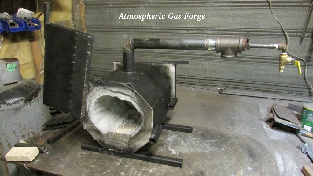
c) Gas Forge / Propane :
A gas forge is basically an insulated box with an attached burner. For general purpose work, it is the restriction of the box that poses the largest problem. Any three dimensional shapes become difficult - if not outright impossible. (Note that for the discussion at hand, many bladesmiths find the general ease of operation and degree of predictable control of gas forges ideal.)
For many, the ease of getting fuel, plus the lack of any requirement for a smoke stack leads them to a gas forge. Although gas burners can certainly be home built, many people are (correctly) concerned about possible fire hazard from poorly constructed burners. Purchasing a commercial burner can vary considerably in cost, but basically the more efficient the burner, the better the fuel economy (especially significant in the long run!)
The second element that effects the overall efficiency of a gas forge is the nature of the insulation. Unfortunately there is a direct relationship between the insulation ability of a material and it's relative fragility - and purchase cost. A simple pile of regular fire place bricks will certainly work. Although low cost, these absorb a significant amount of the energy produced by the burner, resulting in very long warming up cycles. High cost materials like K-Wool blanket are spectacular insulators, but are also extremely fragile.

Gas Forge by David Robertson
You can certainly cobble together a 'firebrick and weed torch' working propane forge for about $50. Commercial forges will run in the $ 400 plus range.

3) Hammers
There is more opinion about what a good blacksmithing hammer is - than anything else related to the work!
A couple of key points :
- It does not matter how hard you hit - if you miss. CONTROL is more important than mere power. This is especially true related to bladesmithing.
- Most tasks can be effectively undertaken with a hammer in the 800 - 1000 gm range (that's 1 1/2 to 2 lbs for the Americans reading).
- A $200 'designer' hammer is not 20 times better than a $10 hardware store ball peen.
- the most useful all-round shape is a classic 'cross peen'.
Yes, individuals will have a specific 'favourite', style, weight, handle. There is a direct relationship between body size to motion dynamic, and so specifics in design in the hammer.
I have already gone into considerable detail on hammers for blacksmithing on earlier articles here :
a bit about HAMMERS
Getting HAMMERED (#1 - Shapes)
Getting HAMMERED # 2 - Dynamics
Getting HAMMERED - #3 Setting Up
 
4) Tongs :
There are more types and shapes of tongs than there are hammers. This is primarily because there is one ideal shape and size of jaws for any given stock profile and dimension. The tongs ideal for 1/4 square are likely impossible to use to grip 1/8 x 1 inch flat bar. (There are of course some styles that suit more than one stock type).
- Tongs are typically one of the first things you learn to make yourself. The resulting quality can vary by a huge amount - often based on how complex the shaping has been. If you look back to the Viking Age tool set shown at the start of this piece - you can see that those are actually pretty simple to forge.
- Because any working blacksmith shop has dozens of 'every day' tongs, and well as many more 'used this one time' pairs, used smithing tongs are fairly easy to buy at 'old junk' type stores. An important point to remember. As a smith yourself, you can always re-forge a set of tongs to a new, more useful to you, shape!
- Although it is certainly possible to use standard pliers to hold especially small pieces, this is hardly ideal :
  - Small jaws mean a loose grip
  - Pliers are designed to fit tight - leaving no room allow a flat grip on anything but the thinnest of metal.
  - Pliers almost always have cut teeth - which will mar the surface of your bar as they grip (especially if at forging temperatures). This can be reduced by grinding off the inner jaws smooth.
  - Many pliers have chromed finishes. If heated, this chrome will vent off - a toxic vapour.
  - Vice Grips are especially to be avoided. Not only are all of the above true, but the heat from the forge will damage the internal springs - making them more difficult to use anyway.

To come : Part Two - Tools for Bladesmithing

I had written another commentary that relates directly to this initial question which also is worth reading. From back in 2009, when that economic downturn caused a lot of people to inquire about 'blacksmith training leading to a business'.


Commercial Message :

Here at the Wareham Forge, I do have a number of training videos that would be of value for those attempting to 'home instruct' .


This three hour program contains a wealth of information, including what to look for in used tools, building a home shop, and demonstrations of a number of basic forming techniques.
Originally filmed in 1992 (on Betamax!) Available as DVD or digital download.


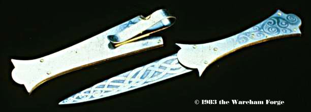
This two and three quarter hour program deals with the historic development of cutting edges and forging technology, as well as demonstrating the methods of producing three reproduction blades.
Originally filmed about 1995 (VHS) Available as DVD or digital download.


This 2 1/2 hour program documents the creation of a number of the forged metal objects created for the 1997 'Viking Encampment' Program at L'Anse aux Meadows NHSC for Parks Canada.
Originally filmed in 1997 (VHS) Available as DVD (digital download soon)

For more details / to order


1) A special note about blacksmithing on video. Any blacksmith will be using the visual appearance of the heated metal to determine working temperatures. However - the camera records light differently than your eyes. Most typically these images show as significantly much brighter on film than they would to your unaided eyes. This is extremely important when assessing bladesmithing. Anything that shows as dull red on video will in fact be well below the minimum correct forging 'critical' temperature. At critical, the metal re-crystallizes, so any force applied will result in cracking - and eventual failure of the metal.

2) Right now, there has been both an increase in price, and shortage in supply, of used, working quality, anvils. The recent popularity of those blacksmithing related TV shows is largely the cause of this. At point of writing, 'fair market price' in Southern Ontario is running about $3.50 CDN per lb. New anvils are certainly available.

3) I have mentioned this often on this blog in commentaries related to Viking Age metalworking.
This becomes a special problem in the world of YouTube - where the objective is not information, but (usually) self promotion. Sure, some person did in fact undertake some stupid method, using the incorrect tools, to achieve poor quality results. 'Possible' is not anyway near 'Correct'. Why would you duplicate this?

4) Or more exactly - 'has way too high a noise to signal ratio'. You can find hundreds of 'I built a home forge' videos. The majority are just plain bad designs.
You will see those trumpeting their 'fire wood' forges (A dry oak camp fire will at best give 1200 C, which you see is the bare minimum forging temperature.) It is not that these designs will not work - it is just that they do not work very well.

5) Consider how light weight charcoal is. Charcoal certainly can produce higher welding temperatures in a well designed forge, and has been the primary fuel used for the bulk of human history. Unless you have the ability to make your own however, you will find charcoal simply way too expensive per working hour to be a realistic consideration.

6) A critical consideration when using solid fuels is the absolute necessity for effective ventilation. Charcoal has one advantage in that once lit, it produces little visible smoke. This is also the case with coke. Technically a coal fire is 'self coking' and this process produces the highly visible smoke and fumes. The fumes from both both coal and coke are toxic. An effective stack / ventilation system is a definite requirement.


Note - an apology to anyone who caught this article in progress over Saturday / Sunday. I managed to hit 'publish' rather than 'draft' - well before this piece was finished. So consequently there would have been multiple versions seen as I continued to work it up. (Some problems connecting my rural internet due to wet weather didn't speed the work either.)

Wednesday, April 15, 2020

‘Careful what you imagine...’


Over the winter months, I had done some combination of consulting, designing and making for a current TV series under production. ( 1 )
This was all related to the possible commission of a ‘Hero Weapon’ for one of the main characters. Obviously, any of us would be very keen to undertake a project like this! The (relative) fame, and potential related sales after the fact, if for no other reasons. Although I have undertaken some object creation for film and television in past years (notably for ‘Outlander’ in 2006), this has been more an outgrowth of my historic based knowledge.
After considerable back and forth about the outline the ‘world’ and details of the character, I found myself constrained by visual elements all ready determined by the costume designer. I did produce a number of weapon designs derived from those outlines, but in the end, none of these proved suitable.
In the course of the discussions, I had also passed along some very vague rough concepts for a different type of weapon entirely. ‘Fortune’ was something inspired (believe it or not) by a song by my friend Heather Dale of the same name. ( 2 )

as chosen from the original roughs final design details

So here is the thing: Film is fantasy - not reality.

Although the lines of the design to the right was where I had been leaning, I envisioned this becoming more like light weight two handed blade, more like an excessively long Japanese katana. The film people stressed the huge size and physical prowess of the actor for whom the the object would be intended for. Although this is certainly true, I cautioned them with the problem of turning something that looked great on paper - into a real world object.
The final design was for an impressive weapon, 6 inches at its widest, tapering to a point at one end but still some 4 inches at the narrow end of the bladed portion, with a total length at roughly 5 1/2 feet. I did some real (!) rough math to estimate the possible weights. Even out of 1/8 thick mild steel I estimated about 10 lbs, which was confirmed when I made a rough cutout prototype. This would prove completely unmanageable as a working weapon (even as a prop in staged fight sequences). The truth is that it does not matter how strong the user is - mass has inertia, which dictates its own limits in combat.

’Staff Weapon’ as completed

So in the end I switched to using 1/4 inch thick aluminum plate. Even then my initial estimate suggested  the final weapon in the range of 8 lbs. The entire project was all cut and grind. (I can just hear my old friend Lloyd Johnston muttering ‘That ain’t Blacksmithing’ ). From a starting piece 8 inches long by 66 long, I used a hand jigsaw to cut out the overall profile. The most tedious part was grinding on the edge bevel, the total was over about 72 inches. This ended up about 3/4 an inch wide, down from the starting 1/4 down to about 1/16 on the edge, but done on one side only (the side that shows in the ‘guard’ position in the final image above.)

Although I am pleased with the overall result, it is hard to say how much (if even any) screen time the final prop weapon may be seen on screen. One thing about film work - so often deadlines are extremely tight. In this case I was not rushed, with about three weeks from chosen concept to final delivery. Film work does pay well however!


1)  Note that I am quite purposely being as vague as possible identifying the show. I’ve learned from past experience that Producers are often insanely secretive about the release of any details, certainly before a film is publicly released (and sometimes even after). 
See the blog post : ’Just who spilt the beans’ - Sept 26, 2006

2) Find the video on YouTube : https://www.youtube.com/watch?v=nl6V9eTn-Tc&list=FLHDqWmXWGPmFXbjilICkQiQ&index=6
How a spark goes through and around to end up so far from the initial inspiration is a long (often contorted) tale of its own.

Saturday, April 11, 2020

'Elkhorn' : ESP

The two previous commentaries have discussed how this work will end up being supported by the Canadian taxpayer (admittedly unintentionally).
Part of the reason I am detailing this whole process, is in an effort to let people get a look at what regularly goes on over the development of a finished work. (Details and complexities often hidden from view.)

'Elkhorn' Coral Element

As I had mentioned in my first overall look at 'Last to See', a big spark that influenced this piece was when I watched 'Ocean Blue' with Silvia Earle. (1)

I was actually shocked as I started to undertake background research into the individual species I would use as the prototypes for the individual component sculptures.
First was the range of effected species. Some, like a number of different sea turtles, I did certainly know about already.
But sharks?
Second was the number of ancient species that now on the brink of destruction - despite having weathered any number of previous mass extinctions. (2)
This combination would become the focus of the selection.


(from my original submission description)
Corals - forged from a combination of pipe and solid bar. Shown as Staghorn and Elkhorn, both Endangered. 240 million years for these types, through 2 Extinction Events.
living Elkhorn Coral
I decided to make this element the first to be constructed. This largely because my intent was to create more of an impression of Elkhorn coral, rather than a more accurate representation.
I have a large amount of 1/8 inch thick mild steel plate, originally sourced as offcuts / scrap on hand here. (3)


Step one was to cut out a set of more or less randomly shaped and sized pieces using the oxy torch. I knew my basic level skill with this tool would result in quite ragged edges. Rather than consider this a flaw, I actually embraced this effect, to create more randomly organic shapes and lines. The size of the individual pieces ranged from about 6 to about 12 inches.
When you look back at the real Elkhorn coral, you can see that I used a more 'mushroom' shaped profile.


The individual pieces were (somewhat intentionally) of a size that would fit easily into my propane forge. Each would be forged into a roughly C shaped profile.


Although the image above was posed with the element cold, it does illustrate the main forging process undertaken for each segment.
Using a bottom dishing stake (this one fits into my post vice), the large end of each piece was dished, most depressed about one inch deep. When doing this, the more ragged edge from the cutting was placed down.
Following this step, some pieces had the 'stem' end contoured but forging with a rounded cross peen against a half circular bottom tool.
Each piece was then given to a roughly C or S shaped overall contour over the horn.
Depending on the resulting contours, these were evened out by working the metal back over a ball stake.


This is all the 24 individual elements after forging, laid out in size order in preparation for welding together.

As it turned out, I had scrounged two pieces of 3/4 diameter steel re-enforcing rod. This material has a set of Z shaped contours on it, which I thought ideal for a central branch / support element. A 24 inch long piece was cut, then forged into a gentle set of random curves. A bolt was welded to the bottom end, which will serve to mount the finished piece through the underlying limestone slab.

Next the individual 'branch' elements were welded on to the upright support


This is the finished piece.
It stands about 30 inches tall, and is roughly 18 inches in diameter.
As completed, all the components have a mottled fire scale surface from the forging. Intentionally, this will rust as exposed to weather once installed in the finished sculpture. In this, it will more closely represent 'dead' coral :


1) I was brought up inside the Canadian Boy Scout movement. This shaped one of my defining characteristics 'Take only photographs, Leave only footprints. (And certainly the cornerstone motto: 'Be Prepared' - which certainly you can see in reflected in my response to COVID-19.) So 'the Enviroment' has long been a major concern for me.
I was involved, at least in a minor way, in the Environmental movement of the early 1970's. We knew, even back then, that Humans were having a major destructive impact on the natural world.

2) I had done considerable background research during the preparation for one of my 2019 ESP entries. The thrust of 'Last to See' was imaging the series of past Mass Extinction events, placing the current 'Holocene' event into context.

3) So far, I personally have not found any problem with materials for this project. As discussed in the earlier commentaries, I only need one type I don't normally hold in standing materials - 2 x 2 inch wire grid. This week I contacted my standard steel supplier, Kreuger Steel in Owen Sound. Although 'to the door' delivery might not be possible, they certainly are able to provide a 'pick up at the gate' purchase.
I may have to source more flat limestone slabs (although I do have a pile of cut stone that would work in a pinch).

Friday, April 10, 2020

(Part 2) CERB and ESP

Part Two : the Canadian Emergency Response Benefit 
and 
the Elora Sculpture Project 
(or - 'So glad I don't live in the USA)


As the Canadians reading this surely know, our various levels of Government responded quickly, based on the available science, to the COVID-19 outbreak. Some might quibble if measures like lock downs were done fast enough. The huge difference in progress of the plague within Canada and the USA demonstrates this clearly. (1)
The Government of Canada announced early that there would be some kind of financial support system enacted to ensure individuals who lost pay because of the 'stay at home' recommendations and increasing closures would still be able to cover their rent, utilities and basic food costs. So far the process has certainly been 'help Canadians FIRST - figure the find details LATER. (2)

As I covered in Part One, I personally have lost all my expected income because of the Government closure of all but 'essential business'. This included two weekend training programs already booked with deposits in April.

So now what?

The other thing intended to undertake over April was building, then installing, this year's entry into the Elora Sculpture Project. (3)
Something important to know is that there is no financial reward involved in participating in the ESP. Entries are chosen via a jury process, and individual artists loan their work to Elora for exhibit over the May to October period. Potentially any piece is available for sale (to be delivered only after the end of the exhibit period). I personally have had work chosen every year since 2013 - but have only ever sold one sculpture (2015 - 'Armoured Fish'). So in total, this has just about put me to 'break even' on the cost of materials for the seven pieces created so far. As each sculpture has typically taken 2 - 3 weeks to produce, any compensation for labour has not happened.

Yes, the first CERB will almost cover the direct losses from my cancelled April courses.
What the second CERB amount will do is partially offset the time I will be using (and the material costs involved) for building the 2020 ESP sculpture 'Last to Sea'

I will leave it up to the reader to determine if this represents 'your tax dollars well spent'...

Part Three : Creating 'Elkhorn Coral' Element


(1) As well as proving the superiority of Canada's Universal Healthcare system.
And the core value of a National Character founded on a principle of Community Standards - over one based on 'Individual Rights'.

(2) Partially for any Americans reading (Canadians know this already)
Initial measures were a direct wage subsidy to employers to help keep workers on payrolls (first 15 %, quickly increased to 75%). Our fairly good Unemployment Insurance system was modified to eliminate any waiting period, and to cover anyone laid off due to COVID-19 effects (either workplace shut down or individual illness).
About a week later, the Canadian Emergency Response Benefit system was announced - a system of payments which would also cover those in involved in the UI system - particularly those self employed like myself.
At least at point of this writing, at the end of the week individuals could apply for the CERB, it certainly appears the mechanism is 'send money NOW - figure out if you really needed the money LATER'. There was no 'needs test' or 'adjusted amount'. Everyone who undertook what proved to be an extremely simple process (despite my earlier concerns and preparations) has been told to expect the first payment within 10 days. (Given the huge volume of applicants, there may end up some delay there - but this should be expected.)
On the 'adjusted amount' side - everyone has been told to expect the identical '$2000 per 4 weeks' payment. Right now the coverage is extended to the first 16 weeks (after March 13). As should be fully understood, this will represent a taxable benefit. So it certainly appears at this date that any 'adjustment for need' is likely to happen via the 2020 income tax mechanism (so into March / April 2021).

(3) See an earlier commentary on how I see COVID-19 effecting the 2020 ESP.

Thursday, April 09, 2020

'Working' during a Pandemic ...


Part One : The self employed artisan on lockdown.

On one side, it's not really that much different than usual, at least for this time of year.

We expect considerable snow here in Wareham. The first years up here (so the 1990's) four to six feet was typical. Every winter you could expect normally at least two periods, lasting a couple of days, when we were effectively snowed in here. I've learned, through direct, nasty experience, that if Don has not managed to get the roughly 1 km from his place to mine with his four wheel drive tractor to blow out my drive? Just to stay the Hell HOME that day. Any normal winter, you should expect the power to go out for a couple of days as well (not necessarily the same storm). In fact, given the amount of wind at Wareham, power could be expected to fail a couple of times over the rest of the year as well.


Over the winter at the Wareham Forge, operations effectively shut down. There is no residual heating system out in the workshop. I normally only run the propane forge from roughly November through to March. Yes, this effectively acts as a space heater. But the shop is at whatever last nights low temperature was. In January and February this is typically - 10 to - 20 C. I keep a heater on my slack (water) tub in an attempt to keep if from freezing solid. Also a heater on the anvil itself. (Remember that otherwise that huge block of metal would also be at - 20 C!)
Honestly - in a normal year I rarely go into the forge in the dead of winter.

Put that all together, and it is not at all uncommon for us to go 10 to 14 days without setting foot off the property in the winter. (Other than shoveling as seen, out to the mail box.) Standard supply and grocery trips on that same turn over. 'Stocking Up' is just how we live in the country.

February 28, 2020
As you should imagine - this all directly translates into 'No Winter Courses'. When I don't even want to subject myself to those workshop conditions, I can not for the life of me imagine asking anyone to pay to endure those conditions! In past years, my first program of the year (two students, use of propane forge) was typically roughly the second weekend of March Break, so the third weekend in March.
This year my first program was not scheduled until the second weekend in April.

Yea.
Like this weekend coming up.

As anyone following the Wareham Forge has likely seen, I have cancelled the courses originally set for April and May. Everything else I had intended to take part in originally through now to at least July 1 has also been cancelled.

Not a surprise, given the situation we all are finding ourselves in.

So where does that leave me, living the 'Carefree Life of the Artist'?
Pretty much screwed - that's where.

Even before I had decided to cancel my own scheduled programs through to at least July1, the few reservations I did have had mostly cancelled themselves. New bookings? Not happening.
So add it up.
Essentially no income over January to March (*). (Or for December 2019 either actually).
Now no income for April and May, and nothing likely for June either.

So, 'Self Isolation' ? Piece of cake. Pretty much the same thing as has been going on here anyway. The only small modification is that we are fixing our supply trips to a minimum of every 14 days plus.

Part Two?
CERB and ESP


(*) Ok, not quite true. I did get some film related work. Consulting, Design, Object, Rental. Last payment still outstanding by the way. (Expect a future blog post on that project.)

Friday, April 03, 2020

Oseberg Tripod and Cauldron - Refining the Measurements


This is a continuation of some recent commentaries:

Wednesday, March 11, 2020
Oseberg Cauldron...

Thursday, March 26, 2020
Oseberg : Putting up the Pot

The following are excerpts from the original excavation report :
Osebergfundet, A.W. Brogger, 1917 (volume 2) (1)

Fig. 76. showing Tripod (#134) and large Cauldron (# 133) / from Osebergfundet

Tripod
(1904 no. 134) Stativ av jern for kjelen 1904 no. 133. Det bestaar av tre like kraftige jernstænger med klør. Hver stang, som har en samlet længde av ca. 1,25 m. er smidd i ett stykke av en solid jernstang. Den ender i tre smaa klør, 6-10 cm. lange. Herfra gaar den opover som en flat firkantet stang ca 45-50 cm. hvorefter den fortsætter som en vridd stang indtil den øverst ender i et langt, flatt, spydspisslignende stykke, hvori er et naglehul. Her forenes saa alle tre stykker og gjennem hullene gaar en kraftig, oventil klinket nagle, som paa undersiden er bøiet om til et øie. I dette er smidd en kraftig krok, som ovenfor kroken bestaar av tre vridde jerntener, ialt ca. 20 cm. langt. I kroken hænger saa jernkjedelen. Høiden av stativet kan altsaa varieres. Som det nu er monteret har det en høide av ca. 80 cm. over gulvet. Stativet er praktisk talt helt, bare loddet paa ett sted. Det laa like ved kjelene i agterskibet ved gravkammer. væggen, se Osebergfundet vol. I p. 49.

Translation by M. Vedeler (2)

.. consisting of three iron bars with claws. Each rod has a total length of approx. 1.25 m. Is forged in one piece by a solid iron bar, each of them ending in three 6-10 cm long claws. The bars are square and flat at the bottom (45-50 cm up from the claws) after which they turn into twisted bars ending at the top in a long, flat, spear-like piece, containing a nail hole. At this point all three pieces are joined together. A riveted nail is threaded through the holes, which on the underside is bent into an eye. A strong hook with three twisted iron teeth (bar segments) approx. 20 cm. long is hanging from the hole. . The iron kettle hangs in the hook. The height of the stand can thus be regulated. As it is now mounted, it has a height of approx. 80 cm. above the floor. The stand is practically complete, only soldered in one spot. It was found next to the pots in the stern by the tomb. see Osebergfundet vol.  I p. 49.

‘The large cauldron that belongs to the tripod’
Jernkjedelen no. 2, i det væsentlige ganske som 1904 no. 114, men noget større og kraftigere bygget. Bestaar som denne av en rund bundplate hvortil er klinket alle sideplatene, som igjen er klinket sammen. Den er noget defekt i platene. Omkring mundingsranden er som paa 114 lagt et hult jernbaand helt rundt. Ørefæstene for hadden er litt forskjellig fra 114`s, idet de her er hele plater. Hadden har samme konstruktion, er vridd et stort stykke i begge sider, ender i smaa opbøiede spiraler. Mundingsdiameteren er ca. 50 cm. Den laa i agterskibet ved gravkammervæggen, Osebergfundet vol. I p. 49, vestligst av de to kjeler opi den laa sakene 1904 no. 131. Til denne kjelen (eller 114) hører ogsaa det tregrenede stativ 1904 no. 134.

(translation via Google Translate, with some additions)

Iron boiler (cauldron) no. 2, essentially just like 1904 no. 114, but something bigger and more powerfully built. Consists of a round bottom plate to which all the side plates are clipped (attached) , which in turn is clipped (attached) together. It is somewhat defective in the plates. Around the mouth of the estuary (top opening), as in 114, a hollow iron band is laid all around. The ear mounts for the hat (handle) are a bit different from the 114's, since these are whole plates. The hat (handle) has the same construction, is twisted over a large piece (section) on both sides, ends in small curved spirals. The orifice (upper opening) diameter is approx. 50 cm. It lay in the stern by the tomb chamber, Osebergfonden vol. 1 p. 49, the westernmost of the two boilers (cauldrons) in the laid cases (??) 1904 no. 131. This boiler (cauldron), or 114 also belongs to the tree-branched stand 1904 no. 134.

Second Cauldron
En stor jernkjele (nr. 114), som nu bare er bevaret i fragmenter. Bundplaten er rund og ca. 24 cm i diameter, den er ophøiet i kanten, hvortil sideplatene er naglet og klinket. Naglene har runde hoder paa utsiden og klinkplater paa indsiden. Sideplatene varierer i bredde, de er ca. 10   13 cm brede. De er klinket til hverandre. Ingen er bevaret helt, men det er vistnok klart at de kraftige plater har været gjort i ett fra bunden til mundingen. Omkring mundingsranden er lagt et ombøiet, hult jernbaand. Ørene for hanken er meget enkle og ender i to flate fliker, som er fæstet til yttersiden av kjelen. Hadden er gjort av en tyk jernstang med firkantet tversnit, som ender i opbøiede kroker og disse igjen i spiraler. Hadden er vridd nedentil paa begge sider, men kantet paa midten. Kjelens diameter over mundingen er 47 cm, dens største bredde er dog nærmere bunden.

Den stod tæt nord for gravkammerets nordre gavl.

Til denne kjele hører antagelig en skjerding av iern (nr. 143) som laa sammen med de andre kjøkkensaker i agterskibet (fis. 75).
(translation via Google Translate, with some additions)

A large iron boiler (cauldron) no. 114, now preserved only in fragments. The base plate is round and approx. 24 cm in diameter, it is raised at the edge, to which the side plates are riveted and clipped (attached). The nails have round heads on the outside and tiles (roves) on the inside. The side plates vary in width, they are approx. 10 cm wide. They are clinked to each other. No one is fully preserved, but it is clear that the powerful plates have been made in one from the bottom to the mouth. Around the mouth of the estuary (top opening) is a curved, hollow iron band. The ears for the handle are very simple and end in two flat tabs, which are attached to the outside of the boiler. The hat (handle) is made of a thick iron bar with square cross-section, which ends in curved hooks and these again in spirals. The hat (handle) is twisted down on both sides, but angled (flat?) in the middle. The diameter of the boiler above the mouth is 47 cm, but its greatest width is closer to the bottom.

It stood close to the north end of the tomb.

This boiler (cauldron) probably belongs to a cut (hanger) of iron (no. 143) which lay with the other kitchen items in the stern (fig. 75).


             original estimates         report measurements

Tripod
shaft length        125 cm                125 cm
shaft stock        10 mm
twisted segment     50 cm                not specified
top flattened        11.5 cm to 20 mm
claw length        6 & 10 cm            6 & 10 cm
hanger length        20 cm                20 cm
hanger stock        7 mm

Cauldron
top diameter        55 cm                50 cm
depth            25 cm
handle distance    27 cm               

display height        80 cm                80 cm
display clearance    10 cm
maximum height    110 cm
maximum clearance    35 cm

So - you can see how my few original notes, and estimates generated from working with photographs and scaled drawings, are at least not so far off the reported measurements.

As I had suggested in the first commentary in this set (Oseberg Cauldron...) the interpretation of the top edge as being a flat, L shaped piece is incorrect. The original report clearly states that there is a single piece added to the upper rim, which then would have been hammered out and over to create the "curved, hollow iron band" as described.

Drawing of Cauldron #133 credit 'A.E. Christens - Nov. 94'


Of interest on the drawing also sent to me by Marianne Vedeler of the large cauldron:

- The bottom, circular plate is shown as flat, rather than dished.
- The drawing suggests a total of 12 individual plates making up the body (not 8 as I had indicated earlier)
- From this drawing, the estimated depth would be 21 cm (not 25 as I estimated)
- The detail shows the construction of the attachment lugs, necked, drawn and folded under (posibly forge welded?)

The main caption reads (best I can manage)
14 side plaler av litt rehslende slorrelse. Tilnarmef sirkelrund funmplate. Plaler ca 1.5 mm bykhe.

(via Google Translate ??)

14 side plates of slightly rehashing slumber (??). Approximate circular funmplate (baseplate?). Plates approximately 1.5 mm thick.

Much later, I had a pair of comments come in from Henrik Olsgaard ( 3) :

the Norwegian ( often similar to Danish in spelling ) word “ slorrelse “ looks a lot like the Danish word “storrelse” which translates as “size” in English.

In the case of “storrelse” , in Danish “stor” means “big” (and to me the suffix ‘relse’ indicates connection), so literally it means “bigness”, which I translate in this context as “size or shape”.

Thinking more about the word  ‘rehashing’ , I suggest it might be an alternate for “replicate” or “equal”, and would give appropriate meaning to – 14 plates of equal size (or shape).

The key data however is the plate count at 14, and the thickness indicated as 1.5 mm. That is very thin plate for wrought iron (I have seen other artifacts measured more into the range of 4 - 6 mm. There is a very good chance that this is actually the 'after conservation' thickness, not necessarily the 'as new' thickness.


1) As mentioned in an earlier post, I did have access to copies of the original report, for a limited time, back in 1994. This thanks to interlibrary loan from the University of Alberta, through the Orangeville Public Library (one of only two sets available in Canada!)
Thanks to Neil Peterson, who has undertaken a massive project of scanning and re-formatting a large collection of Norse related research materials over the last decade (or more at this point - and made these available to members of DARC.

2) With very kind thanks to Marianne Vedeler from the Museum of Cultural History in Oslo. She undertook sending me copies of both some of the related segments, plus translations, despite the fact that at this time the Museum itself has been closed (COVID-19)

3) Henrik Olsgaard commented via the long standing 'Norsefolk' discussion group. This goes way back to the days of e-mail groups (remember those?) and has an on again / off again history. He is another decades long serious re-enactor, and hoby blacksmith, from the San Fransisco USA area.


February 15 - May 15, 2012 : Supported by a Crafts Projects - Creation and Development Grant

COPYRIGHT NOTICE - All posted text and images @ Darrell Markewitz.
No duplication, in whole or in part, is permitted without the author's expressed written permission.
For a detailed copyright statement : go HERE