Showing posts with label objects. Show all posts

Monday, August 10, 2026

Blacksmith's Gloves for a Museum?


this came to me recently :
"The Canadian Glove Museum in Point Leamington, Newfoundland recently contacted OABA requesting a set of bona-fide blacksmith gloves to add to their collection as they are expanding the collection to include more gloves connected to traditional
trades and skilled craftsmanship. They are requesting "a retired pair connected to a Canadian blacksmith, demonstration, major commission, long career, or teaching story.
A well-used pair with visible wear and a short explanation of how the gloves were used would be especially meaningful."
(This is my response to this request)
 
 I have a pair of gauntlet style gloves, retired due to left hand wear and shrinking, which might well fit your description - and although I am based in Ontario, these have a direct connection to Newfoundland.
 

I had added a few short sections, as direct responses to the details requested :

A Canadian Blacksmith...
Scope of Work...
As a Teacher...
As a Demonstrator...


A Commission - in Newfoundland...
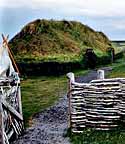
From the mid 1990's I have had a direct association with Parks Canada at L'Anse aux Meadows NHSC. I would be commissioned by Parks to design, construct and implement the 'Norse Encampment' living history program now seen at the site. This would include both the initial staff training and many follow up visits over the years (the most recent in 2023). The original presentation required the creation of roughly 150 detailed objects, and dozens more have been made by myself since. 
In 2000 year I designed and delivered the college level program 'Interpreting the Viking Age' in association with the College of the North Atlantic and the Viking Trails Tourism Assn. at St Anthony. This six week course for adult students would provide the background training for the 'Norstead' attraction.

In 2008 I was commissioned by Parks Canada to create a set of working replica Viking Age ship building tools, This included axes, adzes, chisels, a saw and drills. As research, I would travel to Denmark to the Viking Ship Museum in Roskilde and the Nation Museum in Copenhagen to view artifact prototypes. 
As part of that trip, I would be the only North American invited to participate in the 'Iron Making at Thy' symposium, a practical workshop in bloomery iron smelting. These specific gloves were purchased originally for the needed hand protection working with these furnaces.
Back in Canada, the creation of the axes for this commission would require repeated forge / hammer welding. This process, often seen in images for the dramatic sparks produced, again requires hand protection, particularly for the left, holding, hand. Again this pair of gloves was used. 

 In 2010, I would return again to L'Anse aux Meadows, this time to undertake a full re-creation iron smelt (meaning using all Norse equipment and clothing). Working with the local staff interpreters, it is worth noting that this was the first time iron had been successfully made at L'Anse aux Meadows in 1000 years! This pair of gloves was again employed, not being that much different from a potential Viking Age type.


Looking at the Wear...
Normal practice (for me at least) is to leave the right hand bare, to ensure proper control of the hammer. For that reason there is often more wear to the left, as it is more frequently used, and this is seen in this pair. A split seam on the left thumb was covered with a loop of common hockey tape while welding axes (and yes - I discovered this hole when I got a burn!). A second spit (not covered) is seen on the left index finger. 
As the left hand can be exposed to the extreme heat of the forge - especially during forge welding, this will both harden and shrink the leather. Eventually this will result in a lack of flexibility in the grip which becomes a problem while working. Comparing the two gloves, this shows as both discolouration and the condition of the leather on the left hand.
I would 'retire' this pair of gloves from normal working after the 2010 smelting event. I've kept them to have an additional pair available, even if not in perfect condition, for workshop events. As I have fairly small hands, getting gloves that fit correctly is sometimes a problem. Typically I replace my working gloves about every two / three years - normally due to damage to the left side. (Meaning a lot of mis-matched right hands kicking around the workshop!)
It might be of some interest that right glove has the original price sticker still in place = $33.99. That would have been in 2008 for comparison. I had considered these gloves, which had a good fit for me, well worth the price.
The cuff of each has my 'three lines & three dots' maker's mark inside. This primarily from wanting to keep them sorted at the Danish smelting event.

I appreciate that this pair of blacksmith's used gloves may not show the most extremes of wear. Honestly (and speaking from 45 years experience), a pair of gloves that are over worn may actually not perform the function they are intended for - protection of the hand. I normally only wear gloves when undertaking techniques using the most extremes of heat; forge welding, casting, smelting. Experience has shown that people are too quick to pick up a bar at 'black' heat, (still up too 600+ C) in a gloved hand. This effectively sets the glove on fire, they drop the bar but it is the hot leather than is burning them! Because you can feel the radiant heat with bare skin, merely slowing done before touching generally will keep the experienced smith safe. This combines with the fact that any work in gloves is more clumsy than manipulation with your bare hands.
The main exception here is when forge welding. Proper grip with tongs will leave the triangle between thumb and index finger sitting upwards - and flat. As correct forge welding modern steels requires use of a flux (those sparks seen), not only will extremely hot debris potentially land on that flat surface - it will (painfully!) stick there.


I'm hoping you will consider this pair of gloves, not as much for damage, but as the clear history of use that links directly back to Newfoundland.

(Message to the Canadian Glove Museum was sent on August 10, 2026 - too early yet to know what the response may be.)

Wednesday, July 15, 2026

Alex Hinman at UCV

Once again this year, Lloyd Johnson had organized a demonstration of traditional blacksmithing techniques over a later April weekend at Upper Canada Village in Morrisburg Ontario. This event typically draws about 30 observers, and one of the bonuses is that it's location to the far east of Ontario means a number of blacksmiths from the Montreal region of Quebec also attend. For the 2026 edition, the featured demonstrator was Alex Hinman from Colonial Williamsburg, Virginia. Colonial Willamsburg (CW) is the largest living history site in the USA, which focuses strongly on the American Revolution of 1776. In this the background cultural set, objects, and interpretive presentations are very clearly American Colonial. Alex is one of the principle blacksmiths at the site's re-created Anderson Blacksmith Shop, having come up through the apprenticeship program at CW. The type of work most normally seen in the Anderson shop is production of functional reproductions of more common domestic items as would have been in that shop historically. Work involves coal fires with bellows air, and extensive employing of sledge hammer strikers. The shop is equipped with one forge most typically used for public demonstration type work, with two other forges assigned to more exacting object creation.

Please remember that what follows are my own perceptions and (failing!) memory of what I personally observed. There may very well be errors in these descriptions! Many of the detailed expansions given here were aspects Alex himself provided in discussions.


Alex's physical demonstration centred on the production of three common garden tool objects, well documented in historic catalogues and with physical artifacts. These were a 'Plantation' Hoe, a socketed 5 tine Rake, and a Line Reel.

Importantly, these replicas were all forged from wrought iron, the effective working of this material becoming one of the most significant part of the demonstrations. An important observation for those not familiar with antique wrought iron – it works over a wider range of temperatures than normal with mild steel. Rather than the typical 'bright orange' effective for modern steel, iron needs to be started hotter, often up to the welding temperature. This difference in correct working temperatures means that the time required for the heating cycle usually increased. It is not unusual for cracks to develop along along the encased slag filaments, and the quality of the material certainly varies piece by piece (and sometimes within the same bar).


He would start his demonstration with illustrating simple (?) nail making, this using 1/4 square mild steel. At CW this is actually the standard demonstration object on the public presentation forge, normally carried out by the newest apprentices. (Because of the massive visitor load at CW, the conversation is provided by a second interpreter.) Along with the importance of nail production to the growing Colonies (especially after cutting links with England) Alex pointed out that this was a good light weight task to warm up with physically. This section would include a discussion of the details of the nail making header he used, and various potential construction methods for these tools. One significant detail is that the header used has a slightly domed top. This feature makes it easier for hammer blows to spread the metal towards the edges of the wide head. The square hole on this tool was punched from the bottom upwards, so the smallest diameter was at the top side in use. (This reversed from the shape of much earlier historic heading tools I was familiar with.) During this, in light of questions and further explanations, Alex started to reveal a depth of research and wide knowledge beyond the technical, into the implications of even something as seemingly simple as nails in that Colonial American context. An example he gave was that the standard for a trained, full time, Colonial nail maker was converting 100 lbs of prepared nail rod into 97 lbs of nails, an expectation of only 3% loss in the working.

In the first of his main demonstrations, the Plantation Hoe, Alex would start from a longer piece than required of 2 x 5/8 inch, about 8 inches in total would be used. The first step here was notching and necking in back from the end of the bar, the part that would eventually be formed into the socket.

It was during that work that Alex introduced us all to the 'Williamsburg method' of calling a striker to task at hand. Two ringing taps on the horn was the signal. Alex explained that the ringing sound carries though the busy multi-forge Anderson workshop, despite the observing crowds. Unlike most of us watching, working with strikers is standard there (where many of us work alone, or employing powered hammers or presses). Taking turns at various times as strikers were Josh Koss (seen with Alex below), Megan Carter, and Piper Yorke. (The 'who's up first' confusion was a source of amusement to those watching – but themselves not bold enough to step up.)


The very rough steps of forging this object were :

  • Once notched, the end of the rectangular bar was drawn down (largely on the base of the horn) into roughly 1 x 1 inch square by 4 inches long.

  • The part of this portion of bar closest to the original notch was then spread at 90 degrees to the line of the source bar. This would form the eventual eye of the hoe. As the material was thinned, it was pushed to one side, so there was a straight line down from the wider source bar towards the end.

  • The nub of material remaining at the very end was then also flattened, but this in the the same plane as the starting source bar. This would form the tab that would be welded back on to what would be the underside of the final hoe.

  • The tab was forge welded in place.

  • Then the eye is correctly contoured using a bick and suitable mandrils into a swage block. The widest part of the conical eye is to the bottom side of the hoe. (This allows a simple friction fit over a natural branch handle, thus requiring minimal working of the wood used.)

  • At this point the hoe is cut at the eventual blade end from the parent bar. (If my drawing is correct?)

  • A V shape, wide side roughly the same width as the eye, and point towards the blade end, is fullered in. This will create the central re-enforcing rib.

  • Now using cross peen strokes the blade section is thinned and spread in several directions : backwards towards the eye to create the top corners, sideways to create the width of the blade, forwards to thin towards the cutting edge.

    My own rough notes on the working methods

The piece was roughly finished by pulling the blade to the desired tapering thickness, then using a flatter (again via a striker) to smooth that surface The hoe was completed by drawing a short bevel for the working edge.

With a question about use of a welded 'steeled' edge, the deeper topic of plain iron versus steeled and hardened edges, and how that related to Colonial economics, was discussed.


Completed (rough forged) hoe - Canadian nickle for scale

The next demonstration project was the production of a five tine and socketed rake. All the elements were created from the same 1/4 x 3/4 inch stock bar. The first part of this process was separately making the three teeth that would be fitted into the main body bar (the last two of the five would be drawn from the ends of the bar). It was as these teeth were formed that Alex exhibited a level of control that was as certain as it was subtle. 


    - Working off the end of a longer piece of rectangular stock, the first step was to shoulder in near the end of the bar. This was done by pinching the bar between the back radius edge of the anvil and the cross pean, rather than using a pinch shouldering tool. If you have done this method, the matching of stokes with the cross peen needs to be exact – which Alex performed cleanly and quickly each time.

    - The nub at the end of the bar was drawn out to a short square shaft, keeping the original thickness of the bar. This would form the tendon for eventual joining of the completed tooth to the bar.

    - The shoulder was then squared up by forcing the bar downwards into a punch plate tool.

    - A short section of the bar was then cut off, after the length measured via a caliper. (This would allow Alex to have all his starting pieces at the same length for the remaining teeth.) It was pointed out that the cut should be to roughly the same half way depth into the bar from both sides. This collapses the wrought iron grain equally.

    - The short piece was then drawn to a point, again maintaining the starting thickness (so collapsing the width only). This work was done primarily over the base of the horn, again to speed the drawing process.

    - The last step was to gently curve the completed tooth.

The next teeth would be formed the same way. Alex would check the distance of the separating cut via the set caliper each time. As the next teeth were formed, again the high level of control was illustrated, as each of the next two teeth would be virtually identical to the first. The only comparison I saw Alex make to the first was confirming the curvatures matched as completed.

- (As I remember?) The next step was to pull out the two ends of the main bar into similarly sized and shaped teeth. These would point upwards towards the same edge of the long bar on either end, again formed to match the contours of the earlier teeth. At this stage these are left in the same plane as the flat of the bar. The end teeth are then measured against the others, and the length marked to indicate where eventually these would be folded over.

- One of the separate teeth would eventually be fixed to the centre of the rake bar. The remaining two then will be placed half way between centre and the later end tooth fold. The 1 / 4 point was marked, and square holes punched at those positions. These would be drifted open to match the size of the square tooth shank. One of the reasons to drift open a smaller hole was to distort the iron grain around the hole, rather than cutting the fibres. The swelling from this process would be reduced by hammering down on the bar edge at the hole, with the drift in place to prevent the hole from collapsing.

The next part of the process was to create the separate conical socket for the rake handle. The end of the same stock bar was both flattened and spread (cross peen work) into a thin conical shape. It was during this process that Alex would encounter a problem so familiar to anyone working with wrought iron, fractures when working the end portion of a bar especially with aggressive flattening. Often these fractures make cracks with diagonal cross sections, so an attempt at welding from one edge downwards just ends up making further splitting. An excellent solution to this was demonstrated (see the illustration) :

  • intentionally forcing the edges downwards, causing the splits to open up slightly and the diagonal edges to slide over each other

  • generously fluxing the splits, bringing to a welding heat

  • quickly welding the overlapping splits flat, (hopefully) resealing these cracks


There was a wider discussion from a question : “What would they have been using for flux.” Alex pointed out that borax, used by modern blacksmiths, was also available and widely used in Colonial America. This would have been imported, through England, with the initial source being Turkey. Mention was made of fine white silica sand, often seen in English historical method. A 'backwoods' substitute also known was grinding up the clay nests of mud dauber wasps (because of the very fine particle size).

Once the desired spread of material was created (as Alex pointed out: ' *3* times the desired *interior* diameter, plus a bit for the overlap when welding - pi is for math class.'), the triangle was peened down into the grooves of the swage block. This form would be completed by again forming into the swage block, now working against suitable pointed drift. Alternatives to this were suggested, including using the front step of the anvil. Alex explained that the Colonial anvils run straight from the table on to the horn however.

    • At this point the cone was cut from the stock bar, leaving a short nub that would eventually become the welded joint to the rake bar.

    • The cone was carefully brought to a welding heat, then quickly pushed over a bic, and the two edges welded to close the shape.

    • once completed, the nub at the apex of the cone was flattened, thinning towards the edges all around.

    • Both the centre of the rake and this formed tab were then brought to welding heat. Again, a process taking some care given the differing thickness of materials. Alex then quickly (and seemingly effortlessly) laid up the two separate pieces for the initial weld. This initial tack weld was repeated to ensure the edges were correctly sealed and blended, then the socket slightly adjusted for square and ideal handle angle

Next the two teeth on the ends of the rake bar were bent down to 90 degrees. Each of the three remaining teeth had their posts trimmed to ideal length, then each was held in the post vice. Laying the rake bar over the post, this end was peened down to secure the tooth. Some final adjustment was made to ensure the individual teeth lined up and were square to the bar, and the rake was complete. As finished, the rake was roughly 12 inches wide

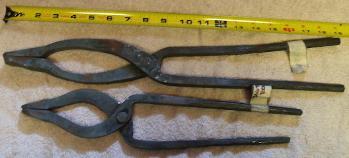
It was during the forging of the rake that Alex would point to the usefulness of his 'side clip' tongs. He pointed out (and would frequently show) how this style was actually more versatile than the full box jaw type. 


It was during the creation of the socket that I noted another tool related fixture seen in the Upper Canada shop. As mentioned, the curving of the socket was done by forging down into a swage block. The shop is equipped with a stand formed from a number of pieces of 4 x 4 lumber strapped together. The timber is sized so that there is a lower slot in the centre, this slot of a width and depth that allows the block to be positioned vertically placing the scalloped edges at working height. The side pieces stand up so the block can also be held horizontally, with curved L shaped brackets on the corners securing it in place. 


The last object demonstrated was a line reel, used in Colonial times to lay out garden rows. The version made was only roughly like the historic illustration below. The construction of the illustration is riveted, where Alex would make the frame of two pieces forge welded together. (I have to fully admit that my description here is less precise, as with my own early packing up and then leaving before completion Sunday, I missed chunks of this demonstration. So the description here not necessarily in the exact forming sequence)


The version made consisted of two main pieces, a rectangular frame with curved sides, mounted to a long central spike. The frame element was formed from 2 lengths of 1/4 x 3/4 x 15" long, and the spike element 20 " of 1/2" round, all again of wrought iron.


The two basically identical L shaped frame pieces were created first :

- The mid point of the flat bar was carefully marked.

- A short tab was flattened on one end.

- One of the sides, from the mid point, was flattened, to about double the original width (so to half the thickness).

- This portion would be given a curve in cross section, by peening into the on hand swage block groove.

- The exact centre of the remaining flat bar side was measured, then a round hole was punched and drifted. Again the swelling of the bar was straightened by leaving the tapered punch in place while hammering down on the edges.

- At the junction between the still straight side and the contoured side, the bar was folded back on to itself and then this seam welded for about an inch.

- Next the contoured side was folded back into the desired L shape, then slightly curved into a bit of a crescent (not flat sided as in the illustration above).

This process was duplicated for the second frame element Then the first corner of the two L shapes forge welded to make a box like form – still left unconnected at one corner.


The next component to create is the central stake :

- First one end of the round rod chosen is drawn out to a long tapered square profile, to a sharp point.

- Using experience to judge what was required for the rough finished length required, the round rod is necked in slightly, once again by careful pinching of the bar over the radius on the far side of the anvil.

- From this point, the bar is drawn down into an even round profile, to a length slightly longer than the distance from top to bottom of the frame. This was checked for easy fit into the two punched holes in the frame.

- Next a small rectangular piece of bar was prepared, roughly 1/4 thick by about 1/2 inch wide, that will form an integral washer that eventually the lower frame will sit against.

- This was cut from the stock bar with slightly slanted cuts, one from each of the two sides. ( / \ )

- This piece was then curved via a groove in the swage block. The prepared central spike element was laid over the resulting U shape, at the place the shift in rod diameter had been formed, then crimped down tightly against the rod. Alex explained the logic of the mirror image diagonal slices, which would ride up over each other as the 'washer' element was welded into place – rather than butt up against each other, creating gaps.

    - Welding this washer into place was the next step. Although you had to be paying attention to see this, he started close to the place the two angled ends overlapped, rotating as he welded, again into the groove. Even with light and quick blows, the washer piece would enlarge slightly, but this would just cause the angled ends to slide over, finishing the weld without a gap.

I would miss the final assembly of this object. Alex was discussing the importance of ensuring the various parts of the forming had to be checked for correct fit, shaping and measurement had to be checked and modified if required before the final open corner was welded together to complete the frame element. The very last step would be peening over the very tip of the central rod to hold the two pieces together – but at the same time ensuring free movement of the rotating frame.


One important addition to the demonstrations was the ability to examine a number of artifact samples of all three objects. These were provided by Alex and also drawn from the (infamous?) Lloyd Johnson Study Collection. One of the aspects of aged wrought iron objects is that weathering often exposes the grain lines. These can inform about the forging processes used, especially things like welding folds and if steeled edges were applied. Along with various samples of various individual's current work, these samples were available for inspection and discussion over evening conversations.


Films referenced during demo

From Alex : “Good evening gents, I know I referenced a lot of historic film in my demo and just wanted to share some of the references.”

Albert Craven, blade forger:

https://youtu.be/UeWH7xEOv_E

Forging surgeon's scissors:

https://youtu.be/xL-VPhZKdeM

Czechoslovak Nailers:

https://www.youtube.com/watch?v=Nma4R8izg9o

Belgian nailers:

https://www.youtube.com/watch?v=3WNvWmQ_ldE

Patterson's spade mill: 

https://www.youtube.com/watch?v=Yu8BGHC7jeA

German file cutters:

https://www.youtube.com/watch?v=JiE3eyMS4Z4

Iranian wire nipper maker:

https://www.youtube.com/watch?v=8LOl0zKcl5s

Pioneer Axe:
https://www.youtube.com/watch?v=Qr4VTCwEfko

Swedish iron puddling and rolling:

https://www.youtube.com/watch?v=z1RSTrGV0NM


Thanks to Lloyd Johnson for providing the starting stock measurements, and suggesting details on the aspects of working with antique wrought iron.

Alex Hinman provided the reference images from late 1700's agricultural implement catalogues. Other images and drawings by the author.

Darrell Markewitz / the Wareham Forge

This article remains copyrighted – please request specific permission before re-printing.

see : https://www.warehamforge.ca/copy.html

This article was created at the request of Lloyd Johnson. It was submitted for the Summer issue of the Ontario Blacksmith's Association quarterly publication The Iron Trillium (in good time), but never included. 

Wednesday, April 03, 2024

the 'French Nail' : Field Expedience

I was recently contacted by a long ago army buddy, who was looking to have some replicas made of an early World War One object. 
Image from the Imperial War Museum

'French Nail' fighting knife ['Clous Français']

The reference he provided was from the Imperial War Museum : https://www.iwm.org.uk/collections/item/object/30003377

These were not 'regular issue' weapons, but were made at the front by blacksmiths working primarily as farriers, who's primary role was shoeing all the horses and mules used for the bulk of transport in that conflict. 

The basic raw material was supplied by converting 'screw pickets', steel posts used for holding strands of barbed wire in entanglements.

Photograph by Lt. J.W. Brooke : 1917-10-23 (IMW)

 The IWM description provides the following dimensions (of the sample pictured above) :

Depth 11 mm

Height 318 mm

Width 54 mm 

Weight 0.314 kg

As is my normal practice, I took the reference image and converted it to life size, and printed off a copy. 

My first surprise is the diameter of the round bar used. I would have expected French metric sizes at 10 mm / 3/8 inch. That 11mm is just a strange size, converting to imperial to 7/16. These knives were also made and used by both British and American troops, where I would expect 1/2 (12.5 mm) stock. Given the few clear reference images I could find of British (hence also Canadian) troops with screw pickets, I decided to use 1/2 round mild steel stock.

In use, the hand would grip inside the ring, around the blade side. The blade would point upwards from the thumb. This allows for a 'low line' stab to the gut. The heavy loop of bar thus runs over the fingers, creating a 'knuckle duster' effect for punches. The knife is primarily a stabbing tool, so the long point is more important than the cutting edges. Simple, brutal, efficient.

From the life size image, I pulled the following additional measurements :

Blade : 20 mm / 3/4 inch wide x 15 cm / 6 inches long

Handle Interior : 80 mm / 3 1/8 long x 30 mm / 1 1/8 wide

The handle interior space was a bit puzzling, being a bit on the small size. I have fairly small hands and would have found the historic sample a tight fit.

The two replicas, upper as diamond / lower as triangle (on 1/4 " grid)

As a primary thrusting weapon, the blade cross section could have been either diamond or triangle - either would produce two cutting edges. The most likely would have been a more standard diamond, but the triangle results in a thicker, and thus more rigid, central spine. None of the images or descriptions I could easily find via the internet specified which. As a forging test, I decide to make one of each cross section. The one closest to the reference sample (smaller hand grip) as diamond. The second replica was made with an intentionally larger interior grip size to fit a more modern physical build, and I used a triangle cross section. I was a bit surprised to find the forging steps required for either turned out to be pretty much the same. The diamond needed forging on four sides, but the triangle I found needed more control with the hammer blows (although admittedly not a shape I make that often).

I also made some trials working 1/2 round into a triangle bottom die. The die I had on hand was more of an equilateral triangle, so not ideal for the wider final shape required. With the proper shaped die made up, the time to forge the triangle cross section would be greatly reduced, and the forging would produce both a significant central spine as well as thinner cutting edges. This most certainly would speed the work if a smith had a large number of requests for this knife. (Worth noting that the sample does not show the more exaggerated cross section suggested by the test pieces I made.) 


Monday, March 18, 2024

History in the Dark - Canadian Museum of History

 I had traveled to Ottawa in later February to give some lecture segments at a local SCA (medieval) event. I took the opportunity to add any extra day to the trip for a visit to one of the many museums in Canada's capital. I had considered both the Diefenbunker, the War Museum, or the Aviation & Space, none of which I had seen before. Truth was I really was hoping to see something that would lead so some artistic inspiration (but not the kind of thing likely at the National Gallery).

So I chose to go back to the Canadian Museum of History, located just over the bridge in Hull.

Now I have not been to what was once the Canadian Museum of Civilization for over a decade. I was well aware, through my contacts in the archaeology community, of the re-engineering of the museum's research, programing and presentation under Steven Harper's government from 2012 -2017. 

As someone fairly familiar with the general sweep of Canadian History, I was extremely displeased with the what had been done.  

It is clear that simple politics has shaped what has been included and how it has been presented.  

The old presentation included simulated room settings to display objects. These started from the impressive West Coast First Nations hall, with timber building fronts and totem poles. As you moved into the modern era, there were recreated street scenes and individual buildings. All used to situate objects in context. A highlight for me was the use of living history staff, mainly working as 'animators', ie presenting set piece historic based and scripted presentations, followed with more free form public interactions. Overall the lighting was bright and the spaces airy. 

As an important aside here, regular readers are aware that I have significant bias here. I have worked as a living history interpreter at a number of Settlement Era sites. I have made many replicas and reproductions for both static and interpretive presentations, plus worked as a consultant on a number of traveling exhibits. Most significant is my creation of the 'Norse Encampment' program for L'Anse aux Meadows NHSC, and my long association with Parks Canada for that site.


The new presentation is dimly lit, overall the feeling is being in a dark shrine to the past. 

A very carefully selected and limited view of the past as well.


The front public spaces now only contain First Nations related objects, primarily major modern sculptural works. Yes, I agree that these are impressive and important pieces. There had originally been a 'European' based diorama as well. This being a representation of the first landing at Vinland by the Norse, with two figures and a detailed replica of a small boat and associated goods. 

This is gone now, who knows where all those pieces ended up? Sorry Mr. Harper, my feeling is that First Nations are being shoved forward, as a tossed bone showing 'see, we know you were here first' Especially since it is the monumental scale *contemporary* work of First Nations ethnic artists being featured to exclusion.  (The fact that "Indigenous peoples, including First Nations, Inuit and Métis" are given free admissions, while all others pay any day but Thursday or Canada Day, kind of re-enforces this.)

" The galleries on Level 1 of the Museum present exhibitions relating principally to Canada’s First Peoples: their histories, cultural identities, artistic expressions and traditional and contemporary ways of life.

On Level 2 there are three galleries devoted to changing exhibitions. Some of these exhibitions are designed by the Canadian Museum of History; others are produced by Canadian as well as international institutions.

The Canadian History Hall is located on levels 3 and 4. This exhibition traces Canada’s history from the dawn of human habitation to the present day. " (quoted from the CMH web site)

A couple of key notes to that description:

Take a look at the allocation of space, via the Museum's printed guide. 

Level 2 also contains the IMAX theatre, the gift shop and significantly the Canadian Children's Museum. Which you should note is not even listed as containing 50% of level two in the description above. 

Level 3 and especially Level 4 are reduced in raw size over the lower levels. The combined exhibit space is about equal to that on Level 1.  (I freely admit that I was getting burned out by the time I got to Level 4, which is 'Contemporary - post 1914', and did not view that. That gallery was brightly lit.)


The Canadian History Hall starts with the Norse in Vinland. (French first, then English, so reduce what you see in half for duplication.) One Panel. Kind of...

Objects? 1) a pile of wood chips, 2) a pile of iron smelting slag. There is absolutely no description or explanation of why either of those fragments mean anything. There are no replicas of the two most significant artifacts, the soapstone spindle whorl or the (diagnostic) bronze ring pin. (There are lots of other replicas other places.)

The next case is 'Arctic People's First Interactions with Europeans' 

Object #8 - number tag is 1cm

Sorry about the image quality, shooting in the dark (see below)

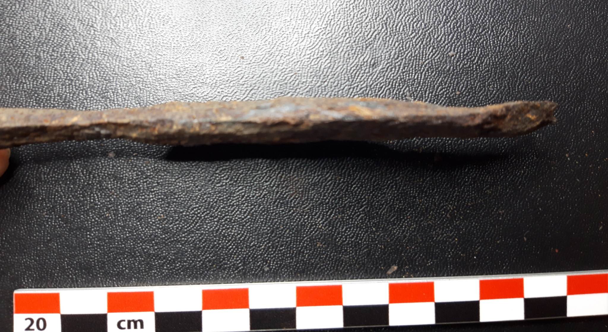
The objects presented include about half that are actually of Greenland Norse origin. It is significant that the objects are actually described as being found in Arctic People's sites, so this origin is hazy at best. Especially the difference between object 10, actually of Arctic People's creation, (and highly significant) and the other two iron artifacts, reworked from broken European objects. (That knife badly photographed as #8 was clearly to my eyes a broken spear tip.) This major technological difference is completely glossed over.

As you proceed through Post Contact Canada, roughly equal space is given to objects from French and English European origins, and those used by First Nations. 9 about 1/3 ?) Primarily these are 'memories of the Rich and Famous' (you know : 'pocket watch of the first Governor of Quebec' ).

Again, Mr. Harper? I understand that you want to ensure that everyone remembers that Six Nations on the Grand River also fought in the War of 1812. But the CMH has already given over roughly 50% + of the total exhibit floor space to exclusively First Nations culture and history via Level 1. 


Looking at the First People's gallery...

Although I do understand there is a simple collections / preservation problem with First Nations materials. The bulk of the objects on display in the First People's Hall, if actually 'historic artifacts', are late 1800's dated. The bulk of these are, as expected, wood or plant material. Many objects are in fact of completely modern creation, and made by First Nations artisans. These are most often not listed as 'replicas' or 'reproductions' however (1) They are simply credited to the artisan with the actual production date. 

Double images on object descriptions from shooting through glass

Note the complete lack of any detail here. This does say 'model' (one of the few so described). Is this life sized? What is it made of? What is the history behind this? Fish trap used how? What is 'Haisle' (a Nation, a Location?) Without proper context, there can not be understanding.

Another bias point. When I was researching 'What Dreams They Had' I ran into a huge problem deciphering the difference between 'traditional' / historical / ancient. Too often 'traditional' came down to 'what my grand mother told me' - with no appreciation that what was done 200 years ago could possibly be different, Much less 600 years ago = pre-European. 

I found too often the background for objects in this gallery, when presented, completely missed this quite important difference between what is well understood to be a shattered 'tradition', an a possible difference in historic practice. To be fair, the overall gallery presentation is attempting to illustrate material culture within separate regional Nations.

I do understand that museums hand over much of the control to the presentation of their collections to graphic designers, who often have little to no understanding of the objects they are presenting. Drama is more important than clarity all too often. The average viewer does not read beyond a couple of words. Context is only provided by loose groupings of objects, often shoved together for effect more than historic realities. Overall I found much of the First Peoples Gallery suffered from this stripped down information. Especially with simple things like functional objects. Why is that basket in any way different than the last basket presented?

What are the materials used here? What source? Not given on the label!

Shooting in the Dark?

Look, I understand that at least SOME of the objects include paint or dye. Somewhat reduced lighting should be expected. But the First People's and History Hall Level A materials were in the dark. Most especially the 'West Coast Nations' materials. From an artistic standpoint, these were the only materials on display that caught my design eye. Below I will show the images as shot - and after considerable modifications via photoshop. (1) Note that this selection is from objects that particularly struck me as possible inspiration points for my own future work in one way or another.

Painted, this one of the better lit objects!

 
This was so dark, I could not get a usable image of the description.

'Headdress', worn like a helmet


It is hard not for me to assume the whole purpose of the near darkness used in the West Coast Nations section specifically was to create an intentional 'shrine' like atmosphere. I noticed anyone attempting conversation was speaking in hushed or whispired tones. Why?

Now of course I had my drawing book - and did make my own scratch drawings of some of these pieces.

If I am feeling generous, I may undertake a second blog posting illustrating some of the other objects that caught my eye...


1) The only thing I studied at all four years of art school was photography. The camera used here is a 2008 Olympus E-300 (8 mpx) with a 3.5 aperture lens. Most of the exposures were hand held (braced against the case where possible) from 1/8 - 1/4 second exposures. I freely admit my hands are not as steady as they once were. But that does not account for the lack of light to enable even vaguely correct exposures.


Friday, January 13, 2023

Blade find from Belgium??


On 2023-01-13 6:36 AM, "C..." * wrote:

 I am a metal detectorist based in Belgium. I stumbled across your website and hoped maybe you can help me?
I recently found an iron blade, which from my own experience looks very old. It looks like forged iron, feels like it weighs a lot for a small object.
I was wondering if you can advise me of an approximate period it might be from and its use? I have been trying to research it online, it reminds me of a small Viking period knife from the examples I have found. Maybe from the 9th -10th century, so I was thinking maybe mid to late Medieval. I could be completely incorrect though. When I found it a part of the end crumbled off, I believe it was a bit more pointed.

The blade has an interesting slight curve. The area I found it in has human history dating back thousands of years.

I thank you in advance for any help you can provide. Please find some photographs attached.

The original request e-mail, highlighted in bold are the elements that I flagged when I first read it.
Below is my reply, with images provided by "C..." inserted as considered.

Well - a lot to unpack here. Sorry to say I may not prove that helpful. I warn you that you may know much of the following already!


Belgium?
That is likely your first problem. Two World wars that chewed up most the ground, and left so much stuff buried. Very small country, intensively populated and farmed - for like forever...

Find location may provide you with some clues - my advice is first to check the history on the piece of ground where you uncovered the object. If the result is 'too much history to narrow occupation' that pretty much ensures that unless there are significant marks or design to the object, you are just not going to narrow it down.


Iron?
Ok - not copper alloy, but...
One possible narrowing would be distinguishing between post Industrial (c 1855) mild steel, and earlier forms of wrought iron as the material.
Wrought iron - especially very old wrought iron, corrodes in a different and distinctive way. The slag inclusions from its creation in bloomery furnaces often causes it to erode to display a linear grain. Steel on the other hand, more typically erodes with flake like patterns.
Looking at the object, it *appears* more like a 'modern' steel.
You could check this using a destructive spark test - or better still via a (costly) lab test, both for carbon content. Wrought iron has basically no carbon. 


One warning is that the level of corrosion to the object appears limited, not what I would expect from centuries buried. As you surely know, the condition of the ground at location of discovery is a big clue there.

Profile?

First thing that jumps out is the cross section. This is a 'sabre' grind - with a rectangular back, then the angled bevel to the cutting edge. Viking Age blades are basically all V profile grind. This to get the most function out of the least amount of metal. A sabre grind requires more material, but does result in a stiffer blade.This remains the case through the Medieval period - again shifting into the 'early Industrial = 1600's'.

One of the things I do to help me understand photographs is reduce one down to 'size as' and print it off. To help visualize what the original object shape was, I then will extend the lines into what seems a logical profile. 
 
Reduced to life size @ 13.5 cm / 8 cm blade

 The object has an extremely wide and thick back compared to a sharp taper to the cutting edge. There does not seem excessive amount of material missing on the blade side (ie - corrosion or wear effects). Attempting to pull measurements off the images, the back is about 5 mm thick and about 10 mm wide, with the bevel about 15 mm wide. As you mentioned, there is a clear blade side concave curve. (Which has to be intentional, the forging process naturally flexes the blade to a convex curve!) This curve has to relate to the function of the tool. The point, extending the existing lines forward, is very thick and blunt - again obviously for strength. 
 
(showing cutting edge)

All this would intentionally create a tool that was extremely strong, but a relatively blunt cutting edge. The curve would suggest use in a sliding cut action - not a straight chopping direction. Given the total blade length at about 8 - 9 cm, the overall result is an extremely rugged tool - far more than is required for the length. But also one that would not have a very effective cutting edge. (Yes - even with some of the edge material obviously corroded away).

The tang is very short, remains at about 4.5 cm. Good chance it just has been corroded or broken away however, so need to be a bit careful about applying too much to this. That said, it does not taper very much down it's length, which may suggest most of the original remains. Not much (remaining?) for secure mounting into a handle. It does appear thicker at the extreme end than at the joint to the blade however, and is clearly rectangular (close to) rather than circular in cross section. This all may indicate something about the original mounting method. A lot of Norse knives have rounded tangs - which passed through a hole drilled or burned into the hilt material, then secured with a metal disk as the end of the tang was peened over like a rivet.


Overall, I see a short, very strong but blunt blade, more likely to be made from a steel alloy.
My first guess would be part of an agricultural tool - like a tooth from a drag harrow.
Although I admit I am not familiar with the design requirements, another possibility could be some kind of pruning or hand harvesting tool (apples?).

If you can find someone (university?) who has a hand held XRF analyzer, this is basically micro destructive and would give you the relative elemental composition of the material. That might be the easiest way to determine relative technology of the metal itself.

Sorry - this from my computer desk and working from such limited information. May not be the commentary you were hoping for?

Good luck with this - and keep looking! Here in Ontario, our history is so relatively shallow (any iron object around my area will be no older than about 1615) - and in comparison so thin. My own home at Wareham was settled (by Europeans) about 1840 - 50. The First Nations just avoided this area, as other than deer and small game, there were no resources available that made the area worth exploiting.


* The images included here are "C..."s. I have intentionally omitted his last name. 

(Note the provision included on the bottom of any longer e-mail replies from me : " To those receiving long detailed replies to specific questions : My own written response may be edited and re-used as a blog posting."

Sunday, June 19, 2022

Viking Age tools for L'Anse aux Meadows NHSC

 Readers : Postings have been absent of late as I was involved in preparing, then delivering, an eight day training program for staff living history interpreters for Parks Canada's 'Viking Encampment' presentation. To accompany this, there was a large order of replicas, two sets of both blacksmithing and woodworking tools, plus four spear heads. 

The tools were ordered from a larger list of previous and potential objects, plus those requested. The primary artifact reference was the larger set of smithing and wood tools found within the Mastermyr Tool Chest (Gotland, estimated to about 1150 AD). Note the distinction between reproductions (generally within 10% of artifacts) and replicas (considered 'of a type' similar to samples).  One difference throughout (unless specifically noted) is the use of modern steels.

One of two forging hammers, reproduction of Mastermyr (final weight was just under 800 gms)

Raising hammer (again reproduction of Mastermyr) and a second similar head with more of a ball shaped head, as a riveting hammer.

Two rivet header tools, based on Mastermyr. The holes themselves a close match to the artifact sample, handles a bit longer and block a bit thinner than the original.

Two of the total of eight different tongs, only loosely based on Mastermyr. Two slightly different styles used for the jaws, as a large number of 'adjusted for stock sizes and shapes' were ordered.

In addition the following :

Leather apron with cast bronze buckle

Double chamber blacksmith's bellows

Two sledge hammers (1800 / 3200 gm)

Pair each of straight cut and round hole punches.


Hacksaws, replicas based on sample from Mastermyr. Modified modern blades for metal / antler (top), for wood (bottom).


Pair of 'flip' carving knives (based on sample from Cantebury), oak slabs. The blades on each were made intentionally to slightly differing profiles to provide for differing carving surfaces.

Two pairs of spoon bits, based on Mastermyr, with wooden breast driver (speculative). The driver was made with a removable collar held by a steel ring. With the top end of each bit as identical shape, this combination allows for changing out the individual bits (two different sizes specified).

Spoon bit mounted for bow driver, bits reproduction from Mastermyr, driver speculative. Bits sized for mounting ship rivets.

Bent neck chisels, replica based on Mastermyr. Made with two slightly different curves of the neck offset.

Group of carving chisels (total eight) Loosely based on Mastermyr samples. Both 2.5 and 1.5 cm sizes, both straight and curved blades.

Two large straight chisels, based on Mastermyr (before mounting wooden handles). Also seen above image at top (after mounting)


Pair of fine trimming adzes, replica based on Mastermyr. Slightly different curvatures to blades.

Knives, total of six : two 'male', two 'female', two carving. All different in shape details, all with antler handles. Top are 'male' / seax blades, uppermost antique wrought iron, second of mid carbon steel. Middle are 'female' / small tool blades, the first of bloomery iron, the second of high carbon steel. Bottom are two different carving shapes, both of high carbon steel.

Four spear heads, no specific prototypes. Top is longer 'fighting' style, remainder smaller 'hunting' types.


February 15 - May 15, 2012 : Supported by a Crafts Projects - Creation and Development Grant

COPYRIGHT NOTICE - All posted text and images @ Darrell Markewitz.
No duplication, in whole or in part, is permitted without the author's expressed written permission.
For a detailed copyright statement : go HERE