Tuesday, May 29, 2007

Preparing an Iron Smelt

I am throwing this up on the BLOG for a couple of purposes. Main reason is that I'm hard into preparing for iron smelting, have a tone of things to get done, and don't have time (or brain power) to get anything else posted up. My readers may also be interested in the amount of work that goes on to prepare for a smelt.

On Saturday (May 26) a small number of folks from DARC came up to help with the preparations for the June 9 smelting experiment.

Our objectives for this experiment are the following:

1) Re-use of existing smelter
The current clay cobb furnace was fired three times in 2006. It looks like with some minor patching the furnace will easily be able to withstand another sequence. We hope to match this furnace to the sequence of patching and re-use seen on excavated furnaces. Objective two relates to this process as well.

2) 'Hot Swap' - a double bloom firing
In the past we have seen that a large part of the charcoal consumed is used to bring the furnace structure up to operation temperature and to create the underlaying slag bowl. If manpower permits, we intend to extract the first bloom, then immediately re-fill the furnace and start straight into a second smelt sequence. A marked improvement in overall raw materials consumed is expected, but it is unknown how this second smelt sequence may develop.

3) Recording debris field
We intend to lay a clean layer of sand over our working area, and make a solid attempt to record both the work patterns and waste deposits that develop. Secondary to this will be collecting all the slags created to better compare total products against ore amounts.

Among may tasks to be undertaken before the smelt itself, preparation of the required ore is by far the most time consuming. On our last trip to Lexington Virginia, Vandy and I picked and packed out 130 kg of rock ore. This material is from one of two abandoned Colonial workings discovered by Lee Sauder and Skip Williams. This is the rock ore DARC has used for a number of earlier experiments, and also the material used for the EARLY IRON series of symposiums.

The first step in preparing the ore is to roast it. Neil and I set up a purpose built fire pit for this, to the left side of the existing smelter. The shallow rectangular pit was walled with brick and had a floor made from heavy steel plate. Richard assisted by chopping all the fire wood required for what turned out to be a several hours long burn. Layers of split hardwood, each roughly wrist thick, were alternated with a layer of rock ore. The fire was assisted with an air blast from our trusty blower.

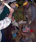
This shows Neil pulling out the larger pieces of heated ore using the bloom tongs. The average pieces were roughly fist size, the largest maybe three times that. Ideally the pieces were heated long enough to bring them up to a dull red. In the fire they needed to at least show an obvious shift from red to a dull black. First the burning wood was removed and set to the sides. The hot pieces were then dumped into a metal bucket filled with water. The largest could be grasped with tongs as shown above. Smaller pieces were scooped out with a flat blade shovel. (The steel plate base made this easy.) The quenching not only cools the material for handling, but more important tends to shatter the structure of the stone. This means easier work in the next phase - crushing for size.

Meghan did the lion's share of the ore crushing - a process that took all afternoon. In the image above Sarah works away with her (and processed about a quarter of the ore total). Individual pieces of roasted ore are pounded with hammers on steel plates to break them down to the sizes required. This is roughly between 'rice to pea' size, with the dust retained. Any rock fragments obvious are also removed and discarded. Over the course of about 6 hours roughly 45 kg of crushed ore was processed.

Along with setting up some of the overhead covers for the work areas, the existing smelter was examined and repaired for the upcoming smelt.
The furnace has been fired a total of three times at this point. Once in June of 2006, then two firings one day after the other in November. The smelter was covered over with a sheet of metal for the winter, but otherwise was exposed to the elements. In the spring it was found that the layout of our new work area was not ideal, and about 5 cm of standing water was pooled at the base of the smelter. Earlier in the year the work area was trenched out and a drainage pipe was installed. Despite this, the smelter structure was found to be in remarkably good shape. It has slumped forward slightly, but there is only minimal cracking. This is assumed to be because the repeated high temperatures from earlier firings have sintered most of the clay cobb to a more durable ceramic.

Most of the repairs required were at the base, around the tap arch. The base of the furnace was deepened slightly, mainly to make it possible to insert a number of standard bricks to support the leaning front edge and create a new tap arch. Patching was done using rough clay, in this case the local 'blue mountain' red. The gap between the irregular base and the replaced bricks was then sealed with clay on both inside and outside surfaces. Next the interior of the smelter was repaired. The last two smelts had eroded the interior wall around the tyere in the pattern seen in past experiments. The wall thickness above the tuyere especially had been reduced to about half, its original - to about 2 cm. With the original contour of the wall restored, the existing ceramic tuyere now only extends about 5 mm into the furnace. This is the same tuyere tube that was used for both of the November smelts, it shows little erosion and will certainly be able to withstand the next smelt.
The last step undertaken was to move both sets of side support bricks forward about 10 cm, This puts the sides just clear of the tuyere on that side and just at the edge of the tap arch on the other. The spaces were filled with the typical smelter debris of charcoal, ash, earth and small slag fragments from the floor in front of the smelter.

Friday, May 25, 2007

'Copper Alloy" ??

A recent discussion on NORSEFOLK has centred on 'copper alloy' cauldrons:

You will see almost any contemporary book - and all excavation reports - list 'copper alloy' as the material.

We have two possibilities here. Copper is almost always mixed with either tin or zinc. The older alloy is copper and tin = Bronze. The amount of tin is not likely to exceed 10%, at that point the material gets quite brittle, almost like glass. Workable bronzes are more likely to be closer to 5% tin. The main reason to add the tin to create bronze is to improve its ability to liquefy and cast it. The tin also hardens the copper, but at the cost of brittleness.

You also will find copper and zinc = Brass. Brass remains workable with fairly high additions of zinc, up to 30 plus per cent. The main reason to add zinc to the alloy is to extend the copper. There is also some increase in hardness, but casting brass remains a problem. It looks like historically, the zinc, plus other things like lead, were added mainly because tin was often hard to get.

(In our modern world, actual bronze sheet is pretty hard to source. Most of us are substituting brass, which is produced in thin sheets commonly available. For making up cauldrons the difference is slight from a cold working standpoint. An important safety note: ZINC FUMES ARE DEADLY!)

So my understanding is that the limiting factor in creating bronze has always been the tin. This is available naturally only at a very few locations. Naturally tin is bound up in hard granite, and almost impossible to mine from rock in ancient times. There were a very rare number of places where tin weathered out of bed rock and was found in alluvial deposits. In ancient times the metal was found in northern Turkey, but those deposits were long exhausted by the Roman era. The other useful source was in England - Cornwall.

During the Viking Age, much earlier ("Roman") bronze objects were melted down and re-cast into new pieces. Any re-use of old metals always results in a loss of both volume and quality. So the Norse metalsmiths would 'cut' their bronze with a number of other metals to extend and 'improve' them. These additions included lead and to a certain extent zinc. Adding lead lowers melting points and improves flow of the liquid metal. It also happens to be toxic, but they didn't know that.

So Viking Age 'bronze' can cover a fairly wide range of potential mixtures, both in terms of metal content and per centages. Hence the modern trend to use 'copper alloy' as the descriptive term.

A side note to this is that many VA cauldrons, certainly copper alloy and sometimes wrought iron ones, are LEAD soldered at the seams. Not something we want to duplicate in our modern re-creations!

(sorry for the lack of articles lately. I am gearing up for several iron smelts in early June. and have been off gathering required materials)

Saturday, May 12, 2007

Oseberg Tripod - Interpretations

Karen suggested (as a comment to the last entry) the use of the Oseberg tripod as a kind of formal 'serving station'

I think she may also be weaving in another tid bit that we both are aware off that may not be known to the group here. Dr. Birgitta Wallace and I have had many long conversations over pots and status. It is her opinion that the medium sized bronze pots (like those found in Mastermyr) were used to heat and serve wine in. This would certainly be a very high end presentation, with the use of a rather expensive specialized object. The cost of the imported wine or difficult to produce mead would also be a display of wealth and gracious hosting.

My counter to this has always been that the main pot from Mastermyr (the cylinder with the slightly dished bottom) was actually described as containing 'food residue'. Certainly suggesting sometimes food was also prepared in that style of pot.

This is a copy of the primary excavation report drawing showing the placement of the tripod and cauldron as they were found in Oseberg. It is scaled, so this may be of great interest to any metalworkers out there.

In the burial, the tripod was found folded. The pot is nearby, but appears to have been laid on its side. This suggests it may have been empty when laid in the burial.

I mention this as I would * expect * that if the tripod and cauldron combination to have been used for formal serving, that in a burial it would have been set up with a food offering. (I am quite aware of the problem with any such * assumptions *)

So Karen's suggestion of the tripod as a piece of high class serving equipment is not to be discounted. Given the technical limits on its use over a fire, her interpretation certainly should be considered.

Thursday, May 10, 2007

Oseberg Tripod - My Interpretation...

This is a version of recent posting to NORSEFOLK. It continues the discussion on the Oseberg tripod, and how I see its design features combine to an interpretation of the context of this specific object inside the material culture of the Viking Age.

When I made my first reconstruction of this object, I was working from three sets of long range information. I had access to the primary excavation report, in Norwegian (which I can't read). So I was only able to read off the recorded measurements, and work from a scaled drawing of the tripod as it was found in the ground. I also had gathered images out of every general work on the Viking Age I had access to, but these showed little detail and generally had no measurements. I also had a number of images shot of the actual object by a friend which showed some of the construction details. I mention this limit on data as I have never personally seen the actual object.

First comment - On the basic design and construction of the artifact:

Remember that the original is made of wrought iron metal, not modern mild steel (the way our reconstructions are). At roughly 1 cm diameter to the uprights, the legs will not bear that much weight before the would start to warp in use. This also drastically limits the structural strength of the design, especially where the upper legs are punched to join them to the basket hook. In historic wrought iron, the tripod is a very light construction overall for its intended use.

The solid pivot point at the top of the tripod fixes the three legs to the central basket. The top of the legs are slightly curved. This all has the result of fixing the angle of the legs. That in turn fixes the spread of the legs, and in turn the mounting height of the tripod itself. The central basket and terminal hook will always have the same clearance above the fire. Note again that this fixed distance is 60 cm (24").

Because the basket hook is a solid piece (made up of three bars welded together) there is absolutely no method possible to raise or lower any attached pot above the fire surface. Any experienced camp fire cook knows you control heat, thus cooking rates, by moving the * pot *. Not by changing the configuration of the * fire *. (The voice of long experience, and often much frustration when trying to teach modern generation cooks!)

The three claws that form the feet of the uprights are a quite intentional design - and intended for use in bare earth. (If you compare the feet to your own hand, it will make this next bit make more sense.) The upright compares to your arm. The three individual prongs are forge welded together to form a 'palm'. This palm is angled back from the line of the upright, something like 30 degrees. (Flex your palm upwards at the wrist, so you can see the back of your hand.) Each of the three prongs curves downward to an angle roughly 90 degrees from the palm section. (Now hook your fingers downward to a claw.)
The end result of all this is that with the legs folded outwards in the open position, the palm section of each leg will run exactly horizontal to the ground. The size of the palm is such that merely stepping on the top surface will firmly drive the points of the three prongs solidly into the earth. This is a quite cleaver and intentional design feature - and one clearly intended for use on bare earth. Driving the prongs into the ground keeps the force from hanging a pot from being born by the holes in the top end of each leg, where the basket hook passes through. That location has the thinest metal of the entire construction.

Use of stones under the feet to elevate the whole unit I agree would allow for producing a useful height for a pot. Perhaps even if large enough stones were used, there might be enough space to allow for a short chain or trammel to control elevation. Resting the claw feet so they hooked over the edge of a rock would be quite unstable however. This method would result in all the force from the pot weight to be born by the thin metal around the punched holes in the legs. This is sure to result in damage to the tripod itself in time.
I have also found that this problem of stress on the construction is most extreme when the tripod is placed on a hard flat surface - a rock ledge, or a modern concrete floor. The legs will balance on the tips of the central prongs only. Any force at all put on the hanging hook causes the legs to try to skate away outwards, so all the stress is borne by those holes in the top of the legs. Also since only the central point is in contact, the legs try to twist sideways adding further stress. (I had made up a wooden plate with holes for the claws to steady the tripod when displayed in an indoor setting.)

It should also be remembered that the actual cauldron found in the same burial will just barely clear the ground when set on to the tripod's hook. The clearance is only about 1 cm. Totally unusable as a cooking set up. (Mind you, would make a impressive way to present beer to ladle out of at a feast!) Did that pot show any traces of fire blackening? Again I do not know. Since there was also a cauldron hanger in the Oseberg burial, the indication of use of the cauldron over a fire does not also prove use of the tripod.

So what I see here is an object intended by its construction and design to be mounted in bare earth, but at the same time, one that also by design is actually not fully functional, primarily as there is no method possible to control cooking temperature.

At this point we have to look to archaeology for further evidence. Certainly in house finds, fires are almost always found set on top of raised platforms. Typically this is a line of stones or stone slabs forming a rectangle that is filled with earth to set the base of the fire a good 15 to 20 cm above the floor. This is not done to aid the cook - but specifically to improve the draft and physical operation of the fire itself. (Believe me, we had a HUGE problem with this whole thing at L'Anse aux Meadows.)

It certainly would be quite possible to create the required clearance for correct cooking if the fire was set into a pit dug underneath the tripod which was correctly set in the ground. So my question here - does the archaeology show the use of such pits to contain cooking fires? (I ask because I do not know.) I would expect a useful size to be less than the diameter of the tripod leg spread, say roughly 50 - 75 cm. In our own use of a replica tripod, I'd suggest a depth of at least 20 cm is required - but 50 cm would be better. This is the kind of feature that should show clearly.

One other thing that very much needs to be addressed:

The Oseberg tripod is an unusual object - and is a * camping * piece of equipment. I mention this because the standard object used in household settings is the cauldron hanger. There are a fair number of samples of chain hangers which run from simple short chains to elaborate decorative forgings of royal status. As I mentioned, there is also an elaborate cauldron hanger in the same Oseberg find.

There is enough * metal * contained in the tripod itself to allow a smith to have constructed a fairly long hanger. The amount of work involved, from a purely technical sense, is quite similar. There are more forge welds in a hanger, but the tripod requires drawing out those long bars for the uprights. From my own work, I certainly would find forging the various small units of a chain less taxing overall than hammering out those long lengths for the tripod!

There are a large number of pieces of equipment in the Oseberg burial that represent travel, rather than home, lifestyle. Consider the wagons / sedges / tents - all mobile equipment (as is the containing ship itself). Although all are functional to a greater or lesser extent, there certainly is a dominance of the highly decorative over the merely useful seen in all.


My conclusion remains that the Oseberg tripod was not originally intended as a functional object. It was instead a purpose made presentation / ritual / symbolic object. For that reason I certainly do not consider it suitable for inclusion in most representations of the Viking Age, unless a specific point about royal versus 'everyday' status objects is the intent.

Wednesday, May 02, 2007

Oseberg Tripod - Measurements

A reconstruction of the Oseberg tripod was recently put forth via NORSEFOLK. Fellow DARC member Karen commented (and was quite right) on the way the illustrated tripod had been extended well beyond
the proportions of the original artifact. She was also correct that any
consideration of just what that object * really * is about from a
cultural sense absolutely requires the correct measurements to be
considered.

So - for a commentary on the significance of the Oseberg Tripod, read my
'Aunt Martha's and Damnthings'

Some images of my past reconstructions of the artifact:

Note that this reconstruction is seen with the small cook pot from
Mastermyr - which is considerably smaller than the cauldron found in the
Oseberg ship burial. Even still you will see that there is absolutely no
room underneath for a fire!

Another reconstruction, shown in place over a fire

I was able to get a copy of the primary excavation report from Oseberg
when I drafted up my working drawings for the tripod. (not on line -
sorry) This included a scaled drawing of the overall excavation with the
tripod clearly pictured, as well as recorded measurements.

(If I've found the correct section of my original notes.)
The length of the individual uprights is about 125 cm
The length of the integral hook is about 20 cm
The twisted part of the legs runs about 50 cm, with 6 sections CW twist
There are THREE claws to each foot
The claws are 10 cm long for the centre and 6 cm for the two sides
The mounted height (ground to top of tripod) is 80 cm
The bars for the uprights are about 1 cm square
The bars for the basket hook are about .6 cm square
The clearance between hook and ground is only 60 cm


I have heard some of the wildest suggestions offered for how to set up
the Oseberg tripod to make it a functional object. My opinion is that
this object was intended only as the * symbol * of a cooking tool, never
as a true working cooking tool. And a Royal status symbol as well. It is
extremely important to remember that this is the * single * sample of
this type of object in existence.

As I have suggested in earlier times when the subject of this tripod has
come up - we all should be using simple wooden pole tripods with a hank
of rope and a couple of links of chain and a hook.

Tuesday, May 01, 2007

Blacksmithing Tools for SALE

I have decided to clean out a large pile of extra tools and equipment I have gathered over the last two decades. Available are portable forges, hand cranked blowers and other related tools. All will be sold on a 'first come' basis. All must be picked up at the Wareham Forge - or some other arrangement to be made (no deliveries!).

I have put up a 'hidden' section on the Wareham Forge web site available HERE

These descriptions include the condition, plus images for a closer view. Prices DO NOT include required PST / GST - Prices in Canadian Dollars.

More stuff may be added as I keep excavating the workshop storage...

Early Pattern Welding Experiments

Published Methods on Pattern Welding - Are they ACCURATE?

> ... the experiments that
> were done at the Museum of The English Rural Life in Reading England. I
> estimate that somewhere in the 1960's a group tried to duplicate several
> patterns found on sword blades. ...
> They found hat if common bars (flat or rectangular) or rods (round) are
> twisted there are gaps in the core of the finished bar. They had better
> results, with both quality if the finished bar and duplication of existing
> patterns, when they placed a rectangular bar between two rods and twisted
> the bundle. The rods would fill in the gaps of the spiral bar for a tighter
> bundle. ...
- 'Carl'

I saw some second hand references to that work when I first starting smithing in the late 70's. Through one of those Serendipity Effects, I had someone show me one of the original reports at a symposium in April. You will also find those methods illustrated in any number more popular books from the mid 70's through - even up to the modern day. (A wonderful example of bad information retained in academic writing. The classic 'Vikings' by shows this suggested process and has been widely copied)

The problem is that the method as described is just not effective.

Any use of round rods in a bundle creates two major problems. First is the very real problem of compressing anything that is made of a number of round cross sections - they just get shoved to one side. One way to solve this is using a half round bottom tool. Often seen in historic shops for making tendons for joints. Taking round rods and twisting them into a bundle will also help solve this somewhat - but accents the second problem.
The second is the gaps left with round sections in a bundle. With any number of rods more than two - there is a large space between them. This would be minimized by use of a bundle of six or seven - which would have one rod in the middle surrounded by a group that just touched around the inside. Use of round rods further creates a large number of V gaps around the outside edges. All of these spaces tend to generate welding flaws, resulting in cracks around the outside surfaces.
A further consideration is that in ancient times raw metal was purchased as short lengths of roughly square 'currency bar'. The wrought iron would have to be hammered out to create those round rods in the first place. (For that reason round profile is rarely seen in pre-industrial objects, unless a specific point about elaborate effort is being made. The cauldron hanger from Sutton Hoo a perfect example.)

I also strongly suspect that the pattern that would be generated from such a method (twisted bundle of round rods) would not give the same physical appearance to the finished object. This strongly indicates an experimental archaeology project!

I've got a new digital camcorder coming in a couple of days. I do want to resume the (so far failed) project to film 'Introduction to Layered Steels', and may include a segment showing the (incorrect) use of round rods. At the very least, its worth making up some test bars and recording still images of the results.

Darrell
 

February 15 - May 15, 2012 : Supported by a Crafts Projects - Creation and Development Grant

COPYRIGHT NOTICE - All posted text and images @ Darrell Markewitz.
No duplication, in whole or in part, is permitted without the author's expressed written permission.
For a detailed copyright statement : go HERE