Wednesday, December 30, 2020

Illustrations of Forge Welding

 ‘Don’t try this at home kids!’

This piece originally written for the Iron Trillium - Ontario Artist Blacksmith Association


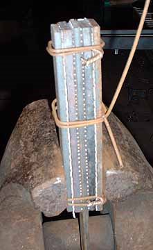
This is the start of my current discontent :


On an estimate, this stack appears about 1 wide by about 3 1/2 + tall by 10 + inches long. (1)

Do any of you see the potential problems here?

I had made a general comment after that first image was posted up on the open discussion :

“ (curious) Are you using a press? Otherwise don't you have problems with the layers 'humping' (*) and making gaps, as you hammer towards the rigidly fixed sections? “
And guess what?
Later there were questions asked ; ‘ Why where there de-laminations of the forge weld? ‘ Which were (predictably) shown to the far end of the billet, to the outer portion of one side. Yes, this was hand hammered (there was a video clip added later as well). Honestly, I considered the hammer choice and the technique shown was just - well, pretty bad (and most likely to aggravate the ‘humping’ problem I mentioned).

Observation # 1 : Don’t believe what you see on the internet. 

Remember that ’90 % of everything is Junk’. (2)

Here is the thing :
You do want to use some method to hold the pile of strips together.
Yes - there is that traditional Japanese approach, where you have what is basically a paddle (rectangular piece on a handle), on which you place a loose pile of plates or pieces. Then oh so carefully heat, then lift over to the anvil, striking with a very wide faced (specialized) hammer to weld. Using great skill not to jumble (much less drop) any of the small pieces.


I learned to prepare my stacks well before I ever had access to a modern electric welder, using several wraps of wire to hold the pieces together. This of course meant I had to pull off the wire loops after the first tack weld course. The wires would certainly weld into the top and bottom surfaces, but would end up bulging out and off the sides. Yes, you do have to use some extra care when heating to welding temperature, that you don’t just burn the wires away. (I find plain ‘black’ electric fencing wire ideal here.) Yes, this certainly adds an extra step, fixing the welded block in the vice and ripping the fragments of wire off. 


An extension of this method would be using a box shaped collar, which would be knocked free once one end of the billet was at least tack welded. (3)

These days, truth be told, I have a big MIG welder, and I usually run a bead fusing one end of the stack together - and also at the same time applying a long bar as a working handle. I personally do this along one end of the plates, not multiples down the sides as seen above. This because the MIG process will ’smear’ the metals combined in the stack, which I certainly don’t what contained in the final layered billet. In practice, I’ve found that I usually get some cracks in the welded pile where the handle is attached anyway. (This primarily because the handle itself acts as a cold shunt.)

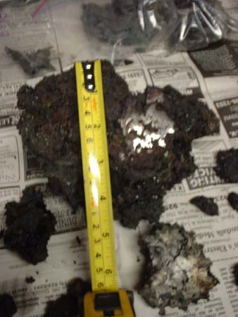
Here two pieces of flattened iron bloom, MIG welded to a handle

Fixing the pile at one end, allows you to run your hammer blows from that point down and away to the open end. This will squeeze out excess flux, and importantly any remaining oxide or dirt, as you hammer from centre to edges, working sequentially down the stack.

Look at the measurements of the stack in that first image yet again :


  • Ideally you want your stack of plates to be *square* in cross section - the height of the stack being the same as the width of the individual bars. This is simply to make sure that you are getting even heat penetration throughout the the whole stack. (4) You can see quite clearly here that the starting stack is easily three, perhaps four times as tall as it is wide!
  • Ideally you want the strips in your stack to be roughly the same width as your hammer face, or not that much wider. (Does not necessarily appear a problem here.) This so you can quickly, and effectively, overlap individual hammer strokes. This to both ensure all parts of the stack get effective hammering, but also to ensure you squeeze out that same flux / impurities from between the plates.
  • Ideally you want to limit the overall length of your prepared pile. There are two reasons here. First is to ensure that the whole pile will come up to both the correct, and importantly a uniform, temperature suitable for effective welding. (In this case, it was later shown the individual was employing a propane gas forge. There are other potential problems / method adjustments required for effective welding in a gas forge. One clear advantage is that in a well designed unit, typically internal temperatures are quite even throughout.) (5)
  • The second reason to reduce the length of your starting stack is simply based on ‘how fast can you hammer’? Remember that your stack, especially for that first weld, is rapidly cooling as soon as it leave the forge. The outer layers especially. Even more so the bottom most ones, in contact with the cold anvil. You can mitigate this somewhat by letting the most distant part of the stack hang off the anvil, pulling the stack back towards you as you hammer, more or less in the same spot. (So moving the billet, not chasing the hammer over the surface.) But any way you look at it, you can only work so fast! I would expect anyone would find the temperature would have significantly dropped before they would reach the end of such a long stack (6).

This all suggests that there potentially would be welding flaws most likely to be found to the far end of the stack (away from the handle) and towards the outer surfaces, especially to what ever surface was placed down to the anvil.  ( Guess what ended up happening here? )

( * ) ’Humping’

Ideally you would want to start on the part of the stack closest to you, pushing any flux / debris out of the layers and squirting this away from your body. Because the top layers are directly under the hammer, these distort the most, certainly more than the bottom layers (where the force has to be distributed down through the loose stack of plates. This is going to effectively cause those upper plates to stretch longer than those at the bottom. If you have fixed by welding at this starting point (or have a loosely held wire bundle) This does not present much of a problem. But if you have secured the entire stack with multiple weld lines as seen, what will happen is that as those top layers are effectively forced longer, they will shift forward and then bulge away from the lower plates. If you worked extremely fast, with very careful control of the hammer striking angle, you might be able to both limit and adjust for this as it happens. But given that there is no functional reason (that I can think of) for running multiple securing MIG beads to begin with? ( 7 )

I should also mention (although you must believe me here, see note 1) that in the short video showing the initial weld sequence, the hammer technique is, well, questionable (at best). The smith is striking with the hammer at  a pronounced diagonal stroke. This is certain to impact more distortion force to the upper plates. If the hammer was coming in flat, at least the force would be directed straight down through the entire stack, rather than squeezing the plates forward. Additionally, the physical motion shown is simply horrible. The smith is striking with the left side edge of the hammer, arm away from the body, elbow lifted. This creates a kind of sweeping motion, rolling the wrist. And using what certainly looks like a 1.5 to 2 kg hammer (?).

'Hero' shot of me forge welding (actually a billet of bloomery iron being compacted).

My own experience has been that for the best results, is to run at least two (ideally four) welding courses. I first use the lighter, better controlled, and way faster, 800 gm hammer. I will usually do this twice, giving both the top, then the original bottom, surface a chance to be ‘up’. I consider these to be ‘tack’ welds, securing the individual plates together. Next I will repeat this combination, switching to a ‘next heavier’ hammer (for me this the 1000 gm - I find I can’t move the 1500 with enough speed or control). This ensures deep penetration and sold welding through the entire block.  (Again your mileage may vary here)

Over the years, there has been a LOT of discussion on ‘the right way to forge weld’. Frankly ‘It works for me’ may be the most common statement. There is some science behind this (not what most people think, either). Working *clean* is most certainly the best single piece of advise.
(see a blog post )


Right now I think we all are seeing an absolute explosion of people thinking that now is the perfect time to attempt to turn their hobby into a ‘paying business’. Throwing money into high powered equipment, in place of developing any hand skills. There is a possibility that for a very, very small number, this might actually succeed. Knife *making* (7) is most certainly the ‘flavour of the month’. I’d bet this also annoys OABA members who have been forging blades for years.


1) I’ve specifically chosen not to credit the individual who provided this image, or the later process images / descriptions. (This to remove any possibility of bad feelings over my opinion - this is not from anyone in OABA, or even Ontario btw.)

2) ‘Sturgeon’s Law’ : coined by science fiction author Theodore Sturgeon

3) If you look at Scott Lankton’s several publications describing the making of his Sutton Hoo sword replica, you will see this use of sliding collars.  (available as a pdf)

4) It is actually a bit more complicated that this. The differing carbon contents / alloy composition of the individual bars may also have slightly different ideal welding temperatures. Ideally you want to place either ’sacrificial’ strips, or the metal with the greatest tolerance against overheating, on the outsides (top and bottom).

5) I personally learned to forge weld in a ‘traditional’ coal forge - and continue to this day using coal as my primary method. The size of my fire box has been found to be most effective for welding billets up to at most 6 inches long. My normal starting stacks are roughly 1 1/4 x 1 1/4 x 5 inches long, which I find gives me the best results (your mileage may vary!).

6) Any of you who have seen me demonstrate certainly have noticed that my normal stroke rate is about double of most people. (This due to the ‘high and fast’ circular motion / technique that I use.) Again I find that for anything over about 5 - 6 inches, even this fast method will  just not allow enough time to place the correct sequence of blows over the surface, before the metal has dropped below what I consider an effective welding temperature. (again, your mileage my vary!)

7) On later reflection, there is a possibility that occurred to me, coming from the use of the propane forge. The tight clamping and securing the individual plates may be an attempt to limit oxygen penetration onto the inner surfaces of the plates. (We all know that an oxide scale surface will not weld?) There are a number of reasons that I personally do not consider gas forges ideal for welding. Individual experience is most likely to differ (Good equipment design a critical factor). I will suggest that binding plates together is not a substitute for correct use of a fluxing agent.

8) I (strongly) distinguish between ‘knife making’ (grinding bars to shape and adding handles) and ‘blade smithing’ (forging bars to close profile). This becomes especially clear with much  seen of recent layered steel blades. Billets that have been hand forged will show distortions from this process, which is part of their specific character. Surfaces with geometrically perfect lines obviously have to be ground to shape (often from purchased billets, themselves created using presses).
More fuel for the ‘that’s not blacksmithing’ debate ?


Monday, December 14, 2020

the Labrys - Considering an object

From a recent e-mail :

 I'm looking to get a labry made, obviously custom, as a female I'm looking for something made for full functionality and usability to last for as long as time would allow, eventually to be passed down to my grandsons ... can you give me an estimate of what I'm looking to be spending.?  (1)


I had to look up 'labrys' : https://en.wikipedia.org/wiki/Labrys

Golden minoan labrys ( double ax ) Archaeological Museum in Herakleion (2)

Although you do always have to be careful with the short hand of Wikipedia, the article does match pretty much what I did know generally about double bladed axes in archaeology. Mainly that these rarely existed as objects, and when they did, they were certainly ritual / religious symbols rather than functioning weapons. There are existing (ancient) depictions of the labrys, but these are initially related to goddess figures (so the proportions are clearly unrealistic). 

Modern fantasy artists (blame Frank Frazetta) have often included axes of various kinds - but again there is little realism in the sizes seen. 

'The Snow Giants' Frazetta - 1967

There is an aspect of physical dynamics involved in the 'real' over the 'fantastic'. Even with a long double hand handle, any axe much over 2 kg just can not be controlled in movement. This is certainly proven if you look to Viking Age axes, a time period (particularly from Denmark) when axes became commonly used in combat. Or to lumbering tools from the Canadian Settlement period.
(see a blog commentary related to a different artifact axe)

So one clear decision point for anyone will be to determine if they are desiring what is more a symbolic than a functional object.
(In this case, 'Full functionality' may present a bit of an interpretation problem.)


I usually suggest people take a comparison look at the line of axes made by Gransfors Bruk of Sweden. This company has a long history of forging high quality tool axes. (3) They do make an extremely high quality product, typically mild steel bodies with inlaid carbon steel cutting edges. (I have one of their 'forest axes' myself - and it is an excellent tool.)

the Gransfors Double Bit Axe


Functional double bit axes were common in the 1800's in North America as a standard logging tool. The two edges had slightly different bevel angles, allowing for use for both felling and splitting. You can see G/B offers one, in modern times more commonly used for competition axe throwing (which has been popular the last decade). 
You can see the important details :
- head weight = 2 kg
- blade length = 16 cm
- cost = $480 CDN (plus shipping, any duty)

In actual fact, the closest comparisons available at G/B will be found on their (limited) 'Ancient' line - replicas of Viking Age working tool axes.
 
You can see two examples there, the bearded axe and the (smaller) double lug axe.

Gransfors Double Lug Axe, showing slit eye construction

From the descriptions, the bearded axe is likely the closest to ideal - as these are individually hand forged - and specifically mention an inset carbon steel edge
- head weight = 1.3 kg
- blade length = (not given, but likely in the range of 15 cm)
- cost = $1450 CDN (plus shipping, any duty) 

Gransfors Bearded Axe, showing punched eye construction
 

So - this is the 'standard' for a roughly similar type. Creating a double edge (over a shaped then punched eye, single edge) represents both a different method - and certainly additional work / time (two inset edges to weld and shape).
A rough ball park quote for this specific request (Labrys type) is hard to generate, because exact details on size have not been established.
But *expect in the range of $1500 - $2000 CDN* (plus required HST, shipping)


Now I will warn you that I am certain there are certainly 'wall hanger' versions available - what are basically nothing more than costume pieces. At *best* cast steel heads, if even a size to be realistic in handling. (More likely cast aluminum for wide edges / large heads like seen in films). These things are not actual working tools (despite what may be claimed). If your interest is the visual / ritual aspect, those may suit? 

16 ga (1.5 mm) stainless steel; Viking-style etched pattern; Hollow inside; Double head width - 16 1/8 in (41 cm) Double head heigh - 13 in (33 cm)

Source: https://armstreet.com/store/armoury/fantasy-viking-double-head-axe
'Fantasy Viking Double-Headed Axe' : Hollow stainless sheet, 40 x 33 cm (4)

I would caution you to really look closely at the description and especially the construction details of cheap (mass produced!) products offered. (Taking two pieces of cut out mild steel, then MIG welding these to a section of pipe, may be fine for a Halloween costume - but this is not 'real' in any stretch of the imagination.) 

'Labrys Double Headed Axe' : Cut sheet welded to pipe


Readers who wish to read further commentaries about past axe making projects by the Wareham Forge will find any number here on this blog :

Norse Woodworking Axes
VA Ship Tools - Adze & Broadaxe
French Trade Axe from Bloom Iron
Ship Tools - Adze / Broadaxe


Images are direct links from the indicated web sites

1) Intentionally hiding the original sender. I do warn people, with a tag line at the bottom of any e-mail, that : " To those receiving long detailed replies to specific questions : My own written response may be edited and re-used as a blog posting. "

2) Image by Wolfgang Sauber (linked from Wikipedia

3) I would dispute their definition of their main line of products as 'hand' forged, in fact they have designed (and long used) specialized mechanical hammers and dies. This is a massive investment, but also allows them to fairly quickly produce standardized shapes (with little to no actual hand hammering). (see their web site description ) Note that this does not apply to the 'Ancient Line' discussed later here. Those are individually worked by hand hammering.

4) This object is described as " Forged out of genuine stainless steel ..."

Increasingly the technical term 'forged' is being used to mean 'made'. This is absolutely incorrect - and I consider the worst kind of commercial hype. As the Webster Dictionary also defines 'forged' as : "made falsely especially with intent to deceive" - you do have to wonder!


Wednesday, December 09, 2020

Prototyping

I've commented here before on the 'Iron Triangle' (1). Over the years of this blog, there have been a lot of commentaries related to the 'Artisan's Way' : where ideas come from, and how these get fleshed out from Inspiration, to Concept, to Making.  There have been discussions of the many, many facets that any individual must undertake (and usually attempt to become proficient at) to turn an occasional hobby activity, into a self supporting business. 

This segment is going to take a look at something so often completely forgotten in the creation process - prototyping. 

There is an old parable. The Japanese master was asked : How long does it take you to make a tea bowl? His answer : Twenty minutes to make the bowl. Twenty hours to prepare the materials. Twenty years to learn how. 

Now too often in our modern world, all people see is the 20 minutes. True master's skill looks effortless. People who do not work with their hands do not recognize the endless effort that is required to acquire that level of knowledge, skill and experience. (2) 

In a perfect situation, an Artisan would have some huge stockpile of Knowledge, Skill and Experience that would allow them to effortlessly (??) to select and transform raw materials into a given object.


But let me tell you - that is just NOT how it works.


I had a very loose concept for a large sculptural piece, centered around a large green glass wine carboy I had scrounged years back. I was thinking of a kind of fantastic 'Audry Two' plant form, with the curved flask shape, turned upside down at it's heart. In working out the overall form, I was intending to make a number of tall S shaped elements, using a number of the glass 'bell' jars I had purchased a long time back. (3)

Initial 'hen scratch' concept drawings

This glass flask was quite large, about 45 cm ( * ) at its widest and about 60 cm tall. Unfortunately, the years being stored in the unheated workshop had placed a huge amount of stress into the thin glass. While I was tracing around the piece to create a full sized layout, the vibration of my arm over the surface proved enough to crack off the entire base section of the flask. Obviously I will have to come up with quite different overall design from the initial concept.

I have often poured through 'Art Forms in the Plant World', which is a shortened overview of the work of photographer Karl Blossfeldt (4). With the loss of the large flask, I knew I would have to include some additional organic elements beside the bell jar 'flowers'

Image by Karl Blossfeldt


One of the images I have been stuck by is the one above. Described as 'Common Chili-nettle. Seminal capsules'. The source image is roughly 23 cm tall, 'enlarged 4.5 times', which would make the actual plant segments about 5 cm long. 

Those who have followed my past work have seen I have done a lot of pieces where my starting materials have been structural steel : pipe, angle and channel. Angle, when flattened, easily creates an initial stock with a raised central rib on ones side (and corresponding central depressed line on the opposite). I know this would prove a very simple way to mimic the scalloped surface on the outer, twisted, capsule parts of the seed pod. 

Although there was not clear detail of the interior parts of the seed pods, it was clear that there was some kind of shaped surface inside. This would only be glimpsed at through the gaps in the exterior spiral casings. Even still, including some kind of additional detail to the form I considered important, in terms of creating different visuals at differing viewing distances for the observer. (5)

The central rod shape, which would extend to make the final terminal, was chosen as 1/2 inch ( * ) round stock. As seen in the source image, this would end in some kind of pointed shape, with a taper drawn down towards it. I made a first attempt at this, using an slightly upset point, which was then hammered into a triangle shaped bottom tool. This resulted in a more or less leaf shaped, but three lobed form, flattened to one surface. I was able to make a more or less tri-symetrical shape by using a rounded edge straight line punch, forcing the flat side back into a gap left in the vice. In the end I was not happy with the overall result however. 

So I made a second version, this time starting with a longer square point. I then punched in a line down each of the flat sides of the square as an additional detail. I had started with a fairly generous length, but had cut off the first terminal made, leaving me with about 50 cm of material.

Start of the core part

The first idea I had for creating the core portion was to start with three pieces of smaller angle (1/2 x 1/2 x 1/8 thick) cut to 20 cm length. These were tack welded (admittedly fairly rough!) in three places, both edges, to splay out from the central rod. For the prototype, I used a simple 'cheat' on the ends, just cutting diagonal lines with the band saw for the ends. The lower portion were cuts at about 45, the upper a longer taper. 

Core - twisted

My idea for all this was to twist the fabricated bundle. Nice *idea* - but how exactly do you *grab* that kind of shape? Holding the lower edge (first cooling the bottom 3 cm or so) proved easy enough. Getting a secure grip on the *top* section to apply the considerable force required proved a real challenge. The overall shape presented by the three outward spreading V shapes of the angle was just too much like a cylinder, and my adjustable twisting wrench just kept slipping off! (6) In the end the result of three separate heat to twist attempts was only a 1/3 rotation, as seen above. (With the addition of considerable swearing in process.)

Preparing the outer wrap parts

For the outside wraps of the capsule, I prepared three pieces of wider (3/4 x 3/4 x 1/8) angle, each 40 cm. Again the ends were diagonal cut on the band saw. Here one end (the lower) was pointed to about 45, but the upper was cut to create a reversed shape (so from the ends back towards the center). Then each was flattened, but leaving about 5 cm on the lower end left at the starting 90 degree shape of the angle. These ends were then forged to both offset that tip to about 65 degrees, but also to add a Z shaped offset. (Clearer in the image above?) These pieces were then MIG welded around the lower end of the twisted core bundle. 

Forming the outer capsule

After attaching the outer pieces, the resulting splayed construction was simply far to large to fit back into the forge ! (7) So although tedious and offering a quite different kind of heat application and control effect, I used my oxy-propane torch to apply sequential heat, allowing me to alternately twist around each of the three bands. I used a piece of larger diameter steel pipe as a central form. This allowed me to concentrate on keeping the spacing between the individual bands (fairly?) regular as I worked around and up. Of course on cooling the cylindrical wrapped bands, these tightened around the form. I had enough space at the base to fit a long piece of 3/8 against bottom edge of the pipe to drive it out. 

Completed seed pod element

The last step was forging in the upper part of the three outer wraps. This requires a lot of lighter, controlled blows, as all the pieces are being both pushed into, but also around, to the core as you forge them. You can clearly see the difference in shape caused by this process, creating more of an elliptical profile overall. These upper ends were left 'forge tight' rather than later being spot welded together.

Element mounted

For this project, I will be making the 'stems' of each element out of re-profiled channel (1/2 x 1 1/2 x 1/8 used for the prototype). There are two cuts made in the end to separate the three 'lines' for this element about 10 cm. For the prototype, each of these separate pieces were forged to slightly different shapes : spread wide then spiral curved (right above), flat offset to one side then an open spiral (left above), drawn to a long square point with reversal curve (back side out of view). The main run of the channel is forged using the cross peen along the wider bottom side, into a recessed half cylinder bottom tool. This results in curving that flat side, also narrowing the gap between the two shorter sides (so more of a wide U shape). Next the opposing sides are carefully forced downwards and around - until the original two open edges touch. The net result is a very organic, slightly distorted pinched cross section, with a visible seam line running along one side. 

For the initial prototype, the two elements (pod and stem) were joined by simply driving the tip of the core rod down into the central gap remaining in the stem and allowing to tighten on cooling.


The creation of a prototype, even from skilled and experienced hands, almost always indicates forging problems to solve and modifications required for a more elegant result :

  • I will likely abandon the use of angle in the core bundle. It has proved too difficult to manipulate - and to control the shape generation. 
  • Instead, I will switch to using a bundle of small round rods, still spiral wrapped around that central core. Buy individually cylindrical pointing the upper ends, I will be able to also create an additional element, suggesting flower stamens.
  • The prototype illustrated how starting lengths for the bars needs to be adjusted if I want to retain the same proportions as the plant source. Ideally I would like this element to be considerably longer in relation to its width (as the source is). Using a ratio 'twice the length for the wraps as the core' proved correct for this version, but only a second prototype will show if this remains the case for a longer finished element.
  • The bottom edge of the outer wraps were formed by simple diagonal cuts. To mimic the more slender lines of the plant, these pieces should really be forged to long tapers initially. 
  • A bit more care needs to be taken controlling the spacing between the individual outer wraps as they are coiled around. It is only through these gaps that the details of the core shapes are glimpsed.  


An important consideration also is revealed here : The vast difference between 'one of a kind' artistic objects, and more standard, repetitive objects. I spent a total of four hours generating this prototype element. With the changes suggested, I will certainly need to make a second, hopefully not taking quite so long (and with considerably less frustration). This represents a huge gap in both effort, and time, between 'I think I can make that' and 'I've made that before'.  

Time is money. 

Skilled Time is expensive.

A couple of things to bear in mind...


( * ) In Canada, steel stocks still come primarily in Imperial (inches) sizes. In an attempt to keep 'up to date' length measurements here are given in current Metric dimensions (cm).

1) You can have it CHEAP, you can have it FAST, you can have it GOOD : pick ONE. 

2) Of late, increasingly I am finding that 'quick fix' methods are coming to dominate public perception. This of itself is hardly a new problem, especially in Western / North American culture (I clearly remember when Eastern Martial Arts caught the fascination of the general public in North America. Few caught the subtlety of 'If you can snatch the pebble from my hand' (although I'd bet most reading are familiar. increasingly, I am finding 'I saw it on the internet' becoming a standard statement of the source of 'knowledge'. I consider this almost frightening in implication, especially when coupled with the quite obvious increasing lack of 'critical evaluation' by the viewers. The number of YouTube hits someone has accumulate is absolutely no measure of anything, save perhaps 'instant celebrity'.

3) This illustrates the glass bell jars : 

'Glass Jar Holder' : 1997

 I had gotten these as a clearance item from Ikea, back in the late 1990's. There were a stock of these (at a stupid reduced price), in red / blue / green colours. I had bought ALL they had available. Currently I still have about 45 of these still boxed away!

4) 'Art Forms in the Plant World' is available as a Dover reprint. This a selection of the larger volumes of close up, fine detailed, black and white images :

https://www.goodreads.com/book/show/825481.Art_Forms_in_the_Plant_World

5) Going to stress this overall approach to design. Ideally any object will become much more interesting to the viewer if there are levels of differing 'visual information' to an object as one approaches from some distance. The overall lines will be seen from far away, ideally presenting enough flow that will encourage the viewer to come closer. At an intermediate distance, more of the form of the individual elements becomes seen (the shape of the flattened angle for example).  Closer still, and aspects like surface texture, or 'hidden' details (like the underlaying pod cores here) can be seen. 

6) In retrospect, some kind of special twisting tool, likely specific for this single application, would be needed. Likely a bar with a suitable sized punched hole in the center (to allow passage of the round core rod). Then three prongs attached, each spaced to fit down into the gap of each piece of angle. (??)

7) I certainly would have been able to correctly heat this large bundle in the coal forge - if I had been using it. I don't have any residual heat in my workshop, so by this time of year I switch to using propane when possible. As much for space heating as effective forging. (the 'Dark Side of the Forge' for me!)

Tuesday, November 24, 2020

Holiday Treasures - Museum of Dufferin

Museum of Dufferin : Holiday Treasures Exhibit and Sale
December 1 - December 12

the work of 60 local artisan makers, 

this year including the Wareham Forge 


" 2020 marks the 16th year of the Holiday Treasures Arts and Crafts Sale! The warmth and beauty of the season is echoed throughout the Main Gallery of the MoD with beautiful displays of handmade treasures for sale. Find a gift for everyone on your list this holiday season! "
 

" Due to COVID-19, the MoD is implementing several new health and safety measures for this event:

    •    Shop a selection of items online at dufferinmuseum.shop (store opens December 1) with curb-side pick up, or local delivery to Shelburne, Orangeville, and Alliston!   
    •    Entry to the onsite show & sale will be by timed entry to promote physical distancing. Book your entry date and time online or by phone (https://www.eventbrite.ca/o/museum-of-dufferin-20042706681)
    ⁃    Masks are required when inside the facility
    ⁃    Each Visitor Pass admits up to FOUR people from the same family / ‘social bubble’
    ⁃    Passes timed for 15 minute separation

Museum of Dufferin

Airport Road at Highway 89

(just east of Shelburne)


Available Online from Holiday Treasures

Loom Light candle holder
Hand forged decorative candle holder, based on early Settlement Era 'pendant' candle holders. Includes a bright coloured candle. Each distinctive!
$ 25 ea
Viking Game
Modern interpretation of 'Kings Table', a 1000 year old 'move and capture' game suitable for two players, ages 8 and up.
$35 ea
Introduction to Blacksmithing - DVD
This three hour program contains a wealth of information, including what to look for in used tools, building a home shop, and demonstrations of a number of basic forming techniques.
$25 ea
Historic Bladesmithing - DVD
This two and three quarter hour program deals with the historic development of cutting edges and forging to heat treating of three different blades
$25 ea

Shopping in Person - Small gifts …


Cast Pewter Ornaments and Plaques
Each individually cast in hand cut soapstone holds
$17 and $25 ea

Tendril Hook - $17
Loom Light candle holder - $25
Dinner Triangle - $25
Fireplace Poker - $30
Each hand forged, with individual shaping and details

(seen above)

Viking Game - $35
as described above
(seen above)

Introduction to Blacksmithing DVD - $25
Historic Bladesmithing DVD - $25
‘Forged with Fire’ - perfect for the beginner to get them started on the right foot.

… to One of a Kind Objects

As part of Holiday Treasures find a collection of 10 larger forged objects created by the Wareham Forge :


Candelabras
Wall hanging, table mount and free standing


Glass Hangers
Ranging in scale and complexity, suitable for holding candles or cut flowers
Decorative Bowls
From the ‘Segmented’ and ‘Lines’ series, forged from heavy plate

all prices include required HST

Tuesday, November 03, 2020

Samhain Iron Smelt

image by Kelly Probyn-Smith


Ore Total = 65 kg

Bloom Total = 15.9 kg

Yield = 24.5 %

Elapsed Time = 12 1/2 hours

Team = Neil Peterson / Bram Porter / Rey Cogswell / Richard Schwitzer (compaction)

Full report under preparation

Wednesday, October 28, 2020

65 at 65

An iron smelt event

October 31

Wareham

I have been casting around for some direction to head with the long set of individual iron smelting experiments, now after the better part of 20 years of undertaking.

Start of the insanity : L'Anse aux Meadows - Summer, 2001

 Starting with that initial week long research workshop at L'Anse aux Meadows NHSC for Parks Canada, the first years were spent just figuring out how to even get any iron at all (!) I dragged members of the Dark Ages Re-Creation Company into the madness. It would not be until my 6th attempt (# 4 with DARC) in Fall of 2004, that there would actually be a workable iron bloom produced.

I was lucky to fall in with Lee Sauder & Skip Williams, and Mike McCarthy. Mike would boldly start the original 'Early Iron' symposium series, the four of us forming the 'Gangue aux Fer'

Sauder / Williams / McCarthy (me in the back) - Early Iron 1, 2004

Lee would launch an annual series of workshops at his home base in Lexington, Virginia, running 10 - 14 days every March from 2005 through to 2011. At 'Smeltfest', furnaces were built and fired daily, investigating the individual variables which effected the success (or failure!) of bloomery iron production in small scale furnaces. Over those years there would be a number of additions, with Shelton Brower and Steve Mankowski (of Colonial Williamsburg) becoming other core members. Another significant accomplishment would be the development of the 'Aristotle' re-melting furnace, which we tested extensively in 2009.

Brower / Sauder / DIck Sargent / Williams / Mankowski - Smeltfest 2009

Here at Wareham, the experience and knowledge gained from all this trial and error experimentation would start to be applied 'backwards' towards specific historic historical prototypes, potential equipment, and possible methods - most specifically to those from Northern European / Viking Age archaeology.

The first specific archaeological series was with Kevin Smith, based on his excavations at Hals in Iceland, with experimental work starting in October of 2007. A total of 8 full smelts were undertaken in this series, extending through to October 2016. 

Neil Peterson, Icelandic grass sod furnace - Hals #8, 2016

Part of the reason that the Hals series ran so long is that the DARC team was approached by Parks Canada in 2009 about running a full scale re-creation of the iron smelt by the Norse at Vinland, as a public demonstration event in 2010. A total of five experimental smelts were ran in this initial series, to be followed up later by another demonstration event in 2017. Both these smelts at L'Anse aux Meadows NHSC would use all circa 1000 type equipment, other than required safety equipment.

Mark Pilgrim (LAM) / Dave Cox (DARC) / me, Vinland #5 (at L'Anse aux Meadows), 2010
Other experimental series work has included two projects from early Scotland :

- Turf To Tools at the Scottish Sculpture Workshop (Lumsden, Aberdeenshire). This based on their local Pictish history (so post Roman / pre Viking). This included one test smelt here in Canada, then four at SSW, in 2014. The second segment of the project was in 2016 and was composed of another three smelts in Scotland. There was a third segment planned to complete this overall combination research and artistic project for September 2020, but COVID lead to postponement. 

- Work at the Scottish Crannogg Centre, based on Early Celtic Iron Age. This series has included one test at Wareham, staff training on site in Aberfeldy in 2016, then a demonstration smelt in 2017. 

Uist Corrigan / Eden Jolly (SSW), T2TA, 2016

Along the way :

- The development of an primary bog iron ore analog, based on the physical characteristics of the natural material found in excavations at L'Anse aux Meadows.

- A number of full scale tests of various historic human powered air systems. (experimentation possibly remains here.)

In total, to date I have personally mounted  over 85 individual iron smelts.  The majority have been intended to answer specific experimental questions, or to accumulate enough working experience to allow useful data to be gathered. There have been a significant number undertaken as public demonstrations, at international symposiums, or as training sessions for students.


'What's next?'

When my long time collaborator and smelting partner Neil Peterson was up to Wareham last week (for a day rendering bloom pieces into useful working bars), he asked what the plan was. The last experimental smelt was the 'Bones' test in June. Although there could be a continuation there, truthfully I don't feel there is much insight to be gained that would be worth the investment in materials, time and effort. I had started some background on early Irish bowl furnaces, but not enough at this point to realistically frame a working experimental series based on this. 

We considered the current test furnace, the stone block, built for a second Icelandic research project over 2019. This furnace has been fired four times at this point, and had suffered some structural damage on its last use (course over Thanksgiving).  Given the shift to colder late fall temperatures (below freezing at night, mid single digits daytime) and the general lack of a clear direction, I decided to repair this furnace for one use.

Condition of the stone block after Oct 11 smelt. The red line is where the original lintel stone (above the extraction arch) had broken out.  

I turn 65 just days after the already scheduled Samhain Iron Smelt, set for Saturday 31 October. 

With tongue in cheek, Neil said " 65 in 65. You could smelt 65 kg of ore. "

Now, the largest volume smelts I personally have ever done have been with 45 kg of ore ( Smeltfest 2005). These also resulted in some of the largest blooms, into the range of plus 20 kg. Attempting 65 kg could increase everything by 40 %, importantly the amount of charcoal and raw working time ( * ). Bloom yield also increases steeply with larger ore amounts. I'm not really sure the furnace on hand would contain what likely would be such a massive bloom!

Past use of this specific furnace has shown it will accept alternating 2 and 3 kg charges at the end (this against standard 1.8 kg charcoal amounts, burn rate averaging 14 minutes.) The stone mass has been found to take significantly longer to come up to working temperature (in the past about 2 + hours). With our normal roughly 30 kg ore amounts, the elapsed time of the main sequence has been in the range of 5 hours.That all suggests an attempt at a 65 kg smelt would add about another 3 - 3 1/2 hours to the main smelt sequence, suggesting a total experimental time (first pre-heat to final extraction) of 12 1/2 hours. ( ** ) 


Just recently, the metal bands on my cut wooden barrel slack tub failed. One of the 'mystic' things here is that tub has never been emptied since I set up the forge at Wareham, back in 1990. (This included some water gathered from the point where Black Duck Brook mixes with the ocean, just downstream from the Smelter Hut at L'Anse aux Meadows.) In the process of replacing the bands, 30 years of accumulated iron forge scale was collected. This material, 2.5 kg, had been added to the analog mix being made in preparation for Saturday's smelt. This material is still drying, but there should be at least 30 - 32 kg of analog.

As I have mentioned before, the region around Wareham does not contain any naturally occurring iron ore. This has meant over the years having to use a wide range of types (and quality!) of ores, perhaps more than any other long working team :

- primary bog iron ore - Newfoundland / Denmark

- 'Lexington Brown' limonite - Virginia

- industrial taconite - Ontario / Scotland

- hematite grit - Quebec

- red iron oxide as analog

- black iron oxide as analog

It has occurred to me that I do have plenty of the other ore types we have worked with here over past experiments. Right now I have a good large amount of variable quality Lexington limonite, including a 'smelt's worth' already roasted an partially broken for size. There is also about 40 kg of hematite grit remaining. 

This suggests starting with 6.5 kg of the limonite (pretty much were we started, and a tribute to Lee and Skip), followed by 6.5 kg of the hematite (which actually was the next ore body which we worked with, easily available in Ontario back at that point). The limonite, which I gathered, does tend to be on the lower iron content side. This should be balanced with the hematite, which if anything tends to be too rich (lacking in silica for slag formation). The balance will be the current analog mix.


This is an 'open invitational' event - with limits imposed by COVID.

What that means is that interested individuals may attend, but do need to contact me directly before attending, ideally by e-mail

Core working team is likely to be gathered from those with past experience. Although observers are welcome, this is not a 'teaching' styled event. (Ok - we all know it is hard to shut me up!)

- Masking will be required

- Distancing will be in effect

- Visitors will have no access to the residence. 


( * ) This not strictly true. At the later end of a smelt sequence, charges are typically large, 1 : 1 with charcoal, or even more. 

( ** ) The limiting factor may turn out to be charcoal. Between what I have on hand here, and what Neil has in store, the total looks to be 12 bags / 100 kg. A normal 30 kg smelt typically consumes about 60 kg. Hopefully this will be 'just enough'.

One problem right now is that with COVID, the normally used 'Maple Leaf' brand via Home Hardware is completely out of stock - and back ordered to at least Spring 2021. Recently Canadian Tire was able to secure a bulk order of Royal Oak out of the USA. Neil grabbed a large quantity, but stores quickly ran through that stock.

Friday, October 23, 2020

Rendering some Blooms


My smelting partner Neil Peterson was up again yesterday for another session forging bloom pieces down to working bars. For Neil this is skills development, for me it is nudging me into the forge.

Although hardly conclusive, I thought I would pull together some (very!) rough numbers on ore / bloom / bar. The purpose of these working sessions has been primarily to bring Neil's skill at forge welding and working with bloomery iron (and to further refine my own skills!). For that reason, we have been going through the considerable pile of mainly DARC experimental results. We have been selecting smaller, roughly fist sized fragments or sections, largely because these best fit into on hand forges for effective heating, and also under the dies of the two major power tools available here. Starting with pieces in the 500 gm range also leads to fairly effective hand hammering. (It should be also noted that all the forge work was via a modern coal forge!)

As it turns out, the two bloom pieces chosen are actually from one of the very first, and one of the very last, smelting efforts here.

One element that needs to be considered is that quite intentionally, almost all the smelts we undertake are deliberately on the smaller ore mass side. Our standard is using 25 - 30 kg of ore. As primarily our purpose is to test various variables related first functional furnaces, and later to specific historic prototypes, this has proven a large enough ore amount to certainly generate a viable bloom. These amounts have also tended to result in total bloom sizes in the 3 - 5 kg range. When quartered, you can see this means individual segments (depending on consistency) in the 700 - 1200 gm range - smaller pieces more easily rendered to bar by a single worker. 

As anyone who has made their own bloomery iron knows, it takes a certain addition of ore to 'prime' the system, in my experience typically about 8 kg to create a working slag bowl (1)


The piece Neil chose was a segment of the June 2020 'Bones' experiment. Of itself, this was not aimed at iron production, but actually testing the survival of bone as added at differing spots in the overall smelting sequence. In terms of iron production, this smelt was a disappointment, a low yield and resulting in a very crumbly textured bloom.

Bloom Pieces (6/20) Neil had chosen the bottom centre piece

This was the second working session for Neil using this bloom piece, which started as 407 gms. On his first session, he had collapsed what is obviously a quite fragmented and 'slaggy' piece into a rough 'brick'. This still had major flaws (cracks), especially to the two ends. Neil worked the small piece holding with tongs. A high number of welding steps were undertaken, certainly more than ideal. However Neil was quite new to forge welding as a process (and overall blacksmithing as a skill set). At that stage, the piece had been reduced to 240 gm.

Working Sequence - image by Neil Peterson

Working Thursday (Oct 23) Neil continued, first compressing and welding up the end flaws, then flattening to a 'book' shape. He then scored and folded, rewelding the two half sections (again all using tongs). This 'brick' shape was then drawn out under the air hammer into the bar seen above. Total 183 gm at roughly 3/4 x 5 1/4 x 1/4 inches. Spark test suggested the result was in the range of a mid carbon content (in the range of 50 points - 1/2%) (2)


I had chosen a grouping of small fragments which had previously been slightly compacted, and MIG welded on to mild steel flat bar handles. The selection was mainly because individually the pieces were roughly the same size, but individually really too small to expect much by way of useful size when compacted. As it turned out on examination, these pieces were all from our very first truly successful bloom creation, from Oct 2004. It should be noted that I did not have numbers on the weight of the starting bloom fragments leading to these pieces, which were at least partially compacted. ( 3 )

Bloom fragments : Oct 2004

I left the handle attached to the largest of these pieces, at 219 gm, then stacked the remaining two, at 95 and 165 gm, for a starting total of 480 gm. Although the starting shapes made for a poor fit, I lightly tack MIG welded the pieces together for ease of handling. 

starting fragments - before tack welding together

Honestly, I have hardly been in the forge at all since COVID lockdown started. So I was actually pretty surprised how easily these fragments worked up. Despite the considerable distance between the coal forge and the hydraulic press, I chanced making the first weld compression using the press. The result was a fully welded together flat plate, with the expected ragged edges. These actually welded in fairly nicely, with less lost fragments than I really expected. Early in this process the handy bar stick broke free, so the remainder of the work was done gripping with tongs. There was one large surface flaw that developed (largely the result of the layering of the central and smallest piece as seen above) It occurred that quick transfer on to the air hammer easily welded in this large diagonal crack. There was no second fold and weld (as Neil had done). The end result was a small bar at 391 gm, roughly 1 x 8 x 3/8 inches. This spark tested to a bit less carbon than the mild steel reference bar, so something about 15 points - 1/6 %

The two finished bars (Darrell top / Neil bottom)

As bloomery iron makers, we talk much about the ore to bloom phase yields. This is not really a fair comparison between individuals, or really between individual smelt events. Ore type, iron content will obviously have a major impact on even theoretical results.  Larger volume ore in a smelt seriously impacts expected yields, with minimum amounts needed to get anything, increasing amount also serving to increase not just bloom weight, but also per cent return. 

In this case, there are not good numbers for the initial ore to bloom phase :

Oct 2004 = (minimal) Notes indicate 2.0 kg bloom mass, but no record of the amount of 'Lexington Brown' limonite ore that was used. 

June 2020 = (better!) Notes indicate 2.6 bloom mass, from 24.75 DD2 analog. At 10% yield within a regularly used furnace build and proven method, clearly something else effected the result. The major difference was the addition of several KG of bone (some with meat attached) during the smelt.


Looking at just the starting bloom to working bar phase however, some allowance needs to be made for the skill of the individual workers :

Neil (novice) = 407 returns 183 gm @ 45 %

Darrell (experienced) = 480 returns 391@ 81 %

But honestly, the variable quality of the starting material is most certainly an important factor as well!


1) Certainly a variable dependent on the ore quality / content. (Since 2016) We have been using a method illustrated by Micheal Nissen of Denmark, where the first 3 - 5 kg charges are made of iron rich tap slag retained from an earlier smelt. This has proven to more quickly establish the working slag bowl, thus meaning the following additions of ore go straight into bloom creation. Overall this method will significantly improve overall yields.

2) It is important to note that this kind of 'Spark Test' is at best both relative, and based largely on personal experience. Known bars of known mild (20 point - 1/5%) / spring (45 point - 1/2%) / high carbon (95 point - 1%) are used for comparison. The bloomery bars are air annealed, with the central part of the bar used against the grinder. It is well understood that bloomery iron, by its very creation process, is quite inconsistent in carbon content (top to bottom / inside to outside of the same bloom can show quite different carbon contents. The number of welding heats taken during the bloom to bar operation can effect carbon content. The size of the starting piece, and the number of folds done in the bar creation, will also have an effect in the results.

3) This smelt was # 6 - so very early in our experience. Up to that point we had extremely poor results, we were still trying to figure out how to get much of anything to function correctly. Note taking had not evolved into any kind of standard. This smelt actually was undertaken almost on the spur of the moment (on a wet afternoon, beer was involved). It turned out to be the first attempt at what would develop into the 'Econo-Norse' test / teaching furnace design. Taken altogether, it is amazing we ended up with iron at all!

Saturday, October 10, 2020

"Can you sharpen.."

Yes

But I won't

I am looking to get an edge put on a hewing spearhead I had received as a gift. I just personally do not feel comfortable enough handling it myself as I do not believe I have the proper skill set.

Short answer is that I am extremely reluctant to take on a job like this one.

There are a couple of components to consider here.

1) An extremely important consideration :
The nature of the original work.
You said you had gotten the spear head as a gift. This likely means you don't have the best information on the original maker. This important related to the undertaking of sharpening (to some extent) but most importantly to the results of this work.
You can physically sharpen almost anything. Consider a paper cut!

Sharpening as a process involves some care and precision, and some combination of time and/or tools. Physically, you need to maintain a precise angle with the tools chosen, over the length of the metal, mirror imaged (usually) on the two sides. This is repeated with finer and finer abrasive surfaces. An edge made sharp using a bench grinder will certainly cut effectively. But the result is a ragged edge, which catches on the a material being cut and quickly degrades. By continued polishing of the edge with finer abrasives, the ragged will become smooth, so leaves less and less to catch and tear.

The hardness of the base material determines :
- how thin a physical edge which can be created
* most importantly *
- how durable that sharpened edge will be.

In use, that fine edge starts to wear away. The harder the material, the longer this takes.
The problem with an object from an unknown maker is two fold :

a) What *was* the original material used?

An extreme example : A high tin bronze alloy can be mixed to be harder than low carbon iron - you can cut wrought iron with certain bronze tools. (The main difference is that this high tin bronze is also a brittle as glass, low carbon iron is flexible and will bend rather than break - consider a sword in use?)
In iron alloys, the primary additional element is carbon. It does not take very much carbon to radically change the hardness of the metal. Significant is that hardness almost always increases brittleness. Antique wrought iron typically has next to no carbon at all (which is why antique objects are often so massive looking, more material was needed to give the required strength. Consider old barn hinges as a good example.)
The most common material in our modern world is mild steel. This material has roughly 0.20 % carbon. This is just enough (see below) to possibly be a 'bit hard'. It also remains soft enough to easily machine (or hand forge). Many 'reproduction' weapons are made of this material, simply as a cost factor.
At roughly 0.50% carbon you have a 'spring' steel. This provides a nice balance of potential hardness (so edge durability) against breaking. So again dependent on heat treating (below), this is a simple alloy choice for 'high impact' cutting edges (read : swords).
As you increase up to about 0.75% you get 'high carbon' steels. Good for fine edge but low impact tools - smaller knives intended for fine slicing (skinning knives).

This progression can shift with the addition of small amounts of other elements added to the alloy. The best example is adding nickle - the result being 'stainless' steels. Your home table knives are most likely only 0.20% carbon, but also about 0.50% nickle. With alloy steels, as the combination of additional elements gets more complex, so does the basic quality of the metal itself change. It is possible in our modern world to create iron alloy steels with radical handling properties. How you might work up shapes with those alloys also can become more an more complex. For some of the more elaborate alloys, attempting hand forging is basically not realistic.

Many 'display' weapons are in fact made of lower carbon, stainless series alloys. This allows for ease of manufacture, and ability to create a surface with a bright mirrored surface, which does not rust in normal situations.

Only in China : Described as "hand forged Damascus' - retail price at $250 US

b) What (if any) heat treating process was the material subjected to (this applies to most metals).
Final heat treating is a three step process : Annealing (to release forging stress) / Quenching (to harden the metal to a desired maximum) / Tempering (selectively *removing* hardness as desired) Most people don't understand the difference between Hardening and Tempering.
I'm not going into fine detail here (this can be a very complex topic).
Basically, once a iron / carbon alloy (steel) is heated to a specific temperature, the faster you cool it, the harder it gets (up to a maximum determined by carbon content). Differing cooling liquids result in different degrees of hardness.
(As you might guess, there is a huge about of 'mystical hoo-doo' around all this!)
The harder the existing metal, the more effort is required to physically sharpen it.

How NOT to oil quench a blade!

The tempering process on the other hand is a low temperature mechanism. For ease of description, the tempering effect starts somewhat above 400 F. What that means effectively is great care needs to be employed if any power tools (sanders etc) are used in the sharpening sequence. 

What is the blade for? Draw different tempers depending on use.

So without knowing what heat treating process was used, there is no way to easily tell how hard the produced object even is. This means that it may be possible to sharpen it - but no guaranties at all about how durable that edge will remain in actual use.

As you can see, all this boils down to : "I realistically can have no idea how difficult it will be to sharpen your blade - or how good a job can even be done."


February 15 - May 15, 2012 : Supported by a Crafts Projects - Creation and Development Grant

COPYRIGHT NOTICE - All posted text and images @ Darrell Markewitz.
No duplication, in whole or in part, is permitted without the author's expressed written permission.
For a detailed copyright statement : go HERE