Monday, November 19, 2018

Forge Welding?

This comes up every so often.
How does a forge weld (hammer weld) actually work?

For the novice blacksmith, this is one of the skills that proves extremely difficult to learn. This is partially because the method involves the proper preparation, the ability to closely judge temperature visually, and very precise hammer control, all in combination for correct results.
Confusing this - what actually is happening is typically poorly understood. There is an awful lot of incorrect or misleading information out there. (1)

So I was interested when the following question was posed by Owen Bush of the UK. (Owen, by the way, is most certainly someone * I * consider to be a true master in our field. Especially as a bladesmith, but also as one who smelts iron blooms.) (2)
Why is carbon steel able to be forge welded at lower temperatures than mild steel or wrought iron... I have a few ideas...It could be that it is physically harder than mild steel or wrought iron and more force is applied to the joining of the hammered pieces, as opposed to plastic deformation. Or that the carbon in carbon steel is reacting to reduce oxidisation in the micro climate of the forge weld...or something else... I would be interested in your thoughts?

Jesvs Hernandez answers. (Jesvs is easily one of the smartest people I know, another of the Early Iron Group.) (3)

Let’s look at these two concepts. Solid state diffusion welding vs. liquid state welding. By definition if it is called a SOLID-STATE welding process (like a forge weld) then there is no liquid (oxyacetylene, MIG) and no filler metal (brazing). The metals to be joined may be similar or not. As the name implies the process of joining two metals involves DIFFUSION. Ideally the contact surfaces are as smooth as possible and free of contaminants. Heat and pressure are applied for a given amount of time. Ideally this would be done in a vacuum or immersed in an inert gas atmosphere for metals that form oxides easily. What occurs at the surface level is that both surfaces contact each other, first by touching the little peaks and valleys of the surface together (because even smooth polished surfaces have a certain roughness to them). These tiny peaks deform and link together. This is technically known as CREEP. Temperature and pressure accelerate the creep until the metals (well… the atoms) migrate through the contact points and of the original gaps and only blisters remain. Finally, more material begins to diffuse between the surfaces closing the blisters and creating the bond. The resulting solid will have no gaps and if the same material is being joined, microscopically there will be no visible joint line. All a nice and solid continuous metallic bond as opposed to a covalent, ionic or weak molecular bond like those of London dispersion or dipole-dipole forces.
One advantage of solid-state diffusion bonding is that dissimilar materials can be joined together. Some of its limitations include, that great care is required in the surface preparation. Oxidation and/or contamination of the surfaces would decrease the joint strength and diffusion-bonding of metals with stable oxide layers is very difficult. Luckily for us, some metals and alloys (like the steel we work with) have their oxide films dissolve/decompose/break apart during the bonding and so metal-to-metal contact can be easily established at the interface. It is when the oxide film is stable that the bond is not easy to form. All of you have experienced this to some point. You all have welded steel which had less than clean and smooth surfaces. And yet it welded together. And have had failed welds even with clean and smooth surfaces because some pesky stable oxide layer formed on the surface unexpectedly.
Ok, now. I am getting closer to what I think happens when welding mild steel to higher carbon steel. For that I need to introduce a new concept: Transient Liquid Phase Diffusion Bonding.
It is not liquid diffusion bonding and it is not solid but technically is considered solid-state because the liquid interface only forms temporarily and the liquid solidifies before it cools down. Meaning it solidifies at the welding temperature. Liquid-state diffusion bonding relies on the formation of a liquid phase at the bond. This liquid phase fills in the gaps in the surface and eventually solidifies facilitating the bond. This is what I think happens when higher carbon levels are present in one of the steels being welded. The carbon lowers the melting point just so this transient liquid phase can occur facilitating the diffusion bond.

One of my 'go to' sources for anything like this is always the excellent ‘Iron, Steel & Swords’ by Helmut Foell. The following is an piece of the 'first level' entry : 6.2.3 Welding with Hammer and Fire (4)
Now let's consider contact welding for steel. We certainly don't have atomically flat surfaces, the steel at all times is covered with a thin (some nanometers) oxide, and the crystal orientations don't match because it is a poly crystal anyway.
1) At room temperature 2) 'polished flat' 3) 'perfectly smooth' - grain structure (a) 

If you now heat up your steel to red-hot temperatures in air and thus in oxygen, it simply burns, forming comparatively thick iron oxides called "scale". Scale can grow rather thick; you can get fractions of a millimeter in minutes!
If you bring scale-covered steel in close contact, not much will happen. However, if you put your iron in the reducing part of you fire (deeper inside) in contrast to the oxidizing part (more on top of the flames) you minimize scaling. If you also pour fine-grained "sand" that contains silicon dioxide (SiO2) on the hot steel, you may liquefy the scale. If you now hit the two pieces hard with your hammer, the liquid stuff squirts out at the seams and you get the iron atoms into close contact. Plenty of thermal energy does the rest. Iron atoms will move and bond to other iron atoms. Welding is achieved.
If you keep your material hot enough for a while, grains grow. The grain boundaries formed during welding thus move and become unrecognizable from the other ones. Taken all of that together, there are plenty of reasons why you need to do hammer welding at elevated temperatures.

Forge Welding - The Rules

'Classic' Forge Welding image (but the camera sees differently than your eye!)
So - going from the theoretical to the practical :

1) CLEAN
As you can see from the knowledgeable descriptions above, you can not fuse oxide. So clean off the oxide from the surfaces before you start. Yes - it is impossible to remove all the oxide down to a microscopic level (unless you were working outside of normal air!). But the easiest way to improve your welding ability is polish off that fire scale before you start.

2) FLUX
See Clean
If you don't keep the oxygen out - you have that fire scale (which will not fuse).
The flux, as stated above, liquifies the (minimal?) scale still present, and also both helps keep out possible 'dirt' from your fire - but also carries any of either away under the hammer stroke.
There is confusion here, because antique wrought iron may in fact 'self flux'. This because there is always some amount of slag trapped inside wrought iron from its creation process. 'Good' quality wrought iron will have less of this - and so may still require some addition of flux. All modern steels require flux.
Note that this puts anyone working with propane at a disadvantage. The borax flux typically used in North America absolutely eats through most forge lining materials. A good quality castable refractory flooring can reduce this damage, but at a premium cost.

3) FIRE Control
See Clean (again)
As Helmut warns that during heating, you should attempt to be holding your metal contained in ideally a reduction atmosphere. For solid fuels, this means:
  • - inside a proper 'cavern' fire
  • - balancing air blast for ideal heat creation, with no additional air (oxygen) supplied
  • - welding with a clean, fresh fire (avoiding excess ash)
The old advice here was 'Two Welds on a Fire' (at least for layered steel work).
Note that this puts anyone working with propane at a disadvantage (yet again). This because unless you have a) a very good forge and b) carefully adjusted the fuel / air mix, you are certain to get quick and excessive scaling in a gas forge.

Stack of Bloomery Iron, heating for a Forge Weld (note uniform colour)
4) TEMPERATURE
You need the metal to become just hot enough effectively deform it enough under the hammer stoke to fuse the pieces as described.
NOT 'until you see sparks coming off' !!! (At that point you are in fact burning the metal, damaging its structure. Fine for horse shoes, but not for any critical work.)
How hot is hot enough?
Sorry - this is where the experience comes in.
'I had to learn just what the correct temperature on the surface looked like' is the simple truth :
  • - ideal temperature varies with different steel types (see Owen's original question)
  • - there is a relationship to hammer technique (see below)
One very important element - the entire mass of metal needs to be at the correct temperature point. This means that the interior of the mass needs to be at roughly the same temperature as the exterior. Consider what this means during the heating cycle. Applying heat too fast will overheat the surfaces (burn) before the centre of the mass has reached effective forge welding temperature. (5)

Obviously you need to be able to observe the metal surface. You can NOT do this will unprotected eyes! At the bare minimum, proper didymium safety glasses. Ideally a darker protective lens. (6)

5) Hammer TECHNIQUE
  • - Speed : the metal will only be hot enough to effectively fuse for an extremely short time. So those hammer strokes need to be very quickly applied to the entire surface to be welded.
  • - Placement : remember that the flux serves to wash out any oxide slag and dirt, as well as needs to be displaced itself. So the location of individual stokes needs to :
  1. - work from folds to open edges
  2. - work from centre to outer edges
  • - Force : you need to hit 'just hard enough to fuse the pieces'. No more, no less. If you don't hit hard enough, you will not displace the flux / slag. Or actually force the pieces into intimate contact as required. But at the same time, the metal is extremely soft and plastic at effective forge welding temperatures. Hitting too hard will simply massively distort the material beyond any desired shape.
  • - Penetration : this is certainly related to all of above. Typically a heavy hammer will apply more effective force through the entire mass. But at the cost of limiting the needed speed and reducing the placement of individual strokes.

Obviously personal hammer technique is going to come into play here.
Myself, I normally run my first course of hammer strokes with my (standard) 800 gm hammer, which allows me to work over the entire stack surface with great speed and very good control of individual strokes. This will at least 'tack' weld the pieces, removing all the flux / slag. I then take a second welding heat. As the pieces are now at least loosely fused, it is much easier to ensure a consistent temperature throughout. I then switch to a heavier (for me, 1000 gm) hammer for the second weld course. I can't move this as quickly, but the intent here is to ensure effective penetration through the entire mass.
If I am working larger billets, I will make the next sequence again to welding temperature. Now I switch to the air hammer. This not only ensures full penetration and fusion of the billet - but quickly starts to pull out the block for the next 'stretch and stack' series.

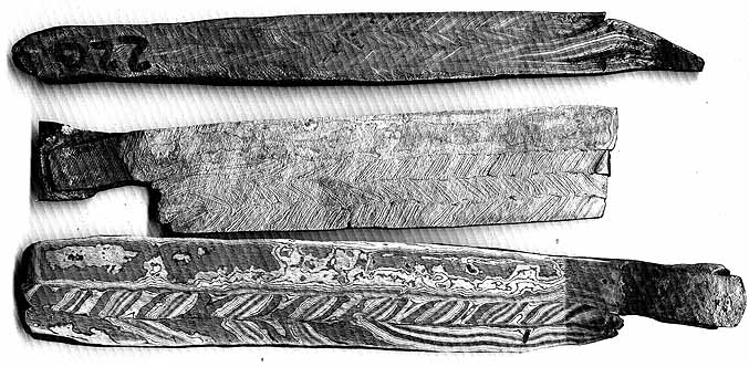
Some Pattern Welded billets - ready for forging into blades. All from about 150 to 200+ 'layers'.

a) illustration stolen from 'Iron, Steel & Swords'

1) I saw a demonstration once by a 'well known name' smith of forge welding. Where he deliberately, one by one, broke all the 'rules' of forge welding. With the repeated tag line : 'See, you don't need to ...'.
I was furious.
Sure, with considerable skill and extensive experience, you might be able to achieve an effective weld after breaking one of the effective rules. But to illustrate to novice blacksmiths that these rules were not important, the overall result was to effectively mystify one person's ability. Not to teach anyone else the technique.

2) A sample illustrating Owen's work and process:

Note that this is a 'high art' * promotional * video.
Also see the elements of work taken from Japanese traditional methods.

3) Unfortunately, Jesvs' web site is down (a loss, as there was a lot of good information there) He still has maintained a good grouping of tutorial style video on YouTube

4) As with all the content on 'Iron, Steel & Swords', this is just the starting point to a more in depth discussion of this topic!

5) This, at the most basic, is why Migration era swords most commonly will have nine layer composition (or sometimes seven or eleven). If you take 1 to 1 1/2 wide plates, each about 3/16 thick, and stack them? The resulting pile will be roughly a square cross section. This allows the heat to evenly penetrate into the stack for most effective forge welding. (Nothing 'mystical' about the number - sorry!)

6) I personally always wear didymium glasses in the forge, especially when working with coal. * For forge welding, I add a pair of 3.5 shade welding lenses, which I have fitted on a 'flip up' mount. This allows me to easily (and safely!) observe the metal surface inside the (too!) bright forge. I can then flip these out of the way so I can correctly see the hammering on the anvil.
With a propane forge - your need may certainly vary.
* The exception here is when teaching. I don't provide didymium lenses to students (for the short time of a course). I need to 'see what they see', so just wear my normal safety glasses.


** ADDITION **

After publishing this piece, I had a direct comment from my old friend (and fellow Artisan Blacksmith) David Robertson of Hammer & Tongs Studio
I read your post. Mostly made sense see also: http://www.phase-trans.msm.cam.ac.uk/2005/Amir/bond.html 

Tuesday, November 13, 2018

'Roman' - MoAF-I : Conclusions

Readers should refer back to recent postings on this topic :
the Mother of All Furnaces - Iron
'Roman' - MoAF-I : Results
What was learned?

1) Intake vs Exhaust vs Height
- The completed furnace, at 185 cm was certainly tall enough to allow for an effective drawing force into the stack.
- There were a number of factors that effected the relatively poor performance of the initial use of the MoAF - as a glass bead making furnace. Certainly one major factor on that first test was that the cross section ratio of intake ports to exhaust was certainly far too large. This may have been compounded by increasing the number of openings over the course of that burn.
- For the use of the same furnace body as an iron smelting furnace, the ratio conformed more closely to the theoretical model suggested by R.H. Rehder (1)
  Rehder's example was   1256 cm2 to 51 cm2 = 24.6 : 1
  MoAF-1 was          706 cm2 to 28 cm2 = 25.2 : 1

2) Charcoal Sizes
For the initial firing of this furnace, the charcoal was sized from .5 to 2.5 cm, our normal 'graded' fuel that has proved effective with our short stack iron furnaces.
With the MoAF-I experiment, this size was increased to 2.5 + / average 3.5 cm, as recommended by Rehder. This larger particle size proved effective in allowing air to flow upwards inside the furnace. Combined with the tall stack height, there was no problem maintaining the correct 'reaction time' for the falling ore, despite the larger gaps between individual fuel pieces.

3) Internal Temperatures
As can be seen on the temperature data, there proved to be no problem generating and maintaining the required temperatures to support the iron smelting process.

4) Type of Tuyere
The effectiveness of the mild steel pipe as tuyeres was a bit of a surprise, in terms of the lack of erosion / shortening of length over the entire burn. In the past, mild steel pipes have proven to melt off inside the smelting furnace, usually burning back towards the furnace wall. This in turn has resulted in excessive erosion of the furnace wall material itself - sometimes to the point of burning completely through!
The effect of the base height (below) may be an important variable here.

5) Base Height
Normally the position of the effective base of the furnace interior is controlled fairly carefully. Past experience has shown a space from base to tuyere of 10 cm is a minimum, with 15 cm the usual amount. This spacing is controlled by using charcoal fines or light wood ash packing in place. (This gap is required to leave room for the developing slag bowl, allowing accumulation of slag and the bloom - without 'drowning' the tuyere air blast).

For the MoAF-I experiment, it was decided to be very conservative in the placement of the tuyeres above the solid base of the furnace. The tuyeres were placed 20 cm above the base.
In the final analysis this large space proved to be an error. The slag bowl was found to form too low, dropping it down below the most effective heat zone inside the furnace. This in turn caused the partially sintered iron to cool below the effective 'welding temperature' needed to allow it to form into a solid bloom mass.

6) Ore?
Since the overall intent of this experiment was getting the needed temperatures, the actual addition of ore was almost an afterthought. Other project commitments had overwhelmed my available time to mix and properly dry a mix of our usual DD1 analog. So in the end we decided to make use of some materials on hand. This certainly proved to be of too low iron content, or not enough amount, to expect good bloom formation.

7) Bloom?
There certainly was effective reduction of iron oxide ores, with accumulation of the resulting iron metal. The overall lacy consistency of the resulting mass however does suggest a number of potential problems as the cause:
- Too small an amount of raw ore / of too low an iron content?
- Incorrect placement of the base below tuyere, cooling the iron below welding temperature to allow compaction?
- Generally a low air volume in the system, which has been shown in the past to result in both lower yields and less compact blooms.


Into the future?

At this point I have observed two other attempts at operating a full scale 'Roman' iron smelting furnace, 150 cm + internal diameter and 200 cm + taller. Neither of these attempts resulted in any effective iron production. There was a large amount raw materials required, and massive amount of expended labour for the construction. The amount of charcoal consumed was huge, with firings running days, rather than hours. All of this certainly beyond my resources here at Wareham.

The build for MoAF took a combined team of six, a full working day to construct. The materials required were over twice the amounts used for the typical 'short shaft' furnaces. As this particular firing was undertaken, the overall consumption of charcoal was in the same order as with the more complete sequence more typical.
It would likely prove quite possible to use ceramic 'flue' tiles for the upper stack portion of this type of furnace, which would speed construction considerably, and reduce materials costs.

Likely the most important factor that will influence continuing an experimentation series based on the Roman, passive tall stack builds was contributed by Neil Peterson:
'Just how many different historic periods do we want to investigate?'


1) 'The Mastery and Uses of Fire in Antiquity' by J.E. Rehder - 2000
McGill-Queen's University Press, ISBN 0-7735-2067-8 

Friday, November 09, 2018

'Roman' / MoAF-I : Results

(continues a rather lengthy post describing the furnace build)

One thing to remember here is that the intent of the Nov 3 experiment was to record internal temperatures = to see if high enough temperatures would be produced, and maintained, to allow for potential iron smelting.

In this, the effort can be seen as a success. Thanks to instrumentation provided by Neil Peterson, there was much better temperature data records than normally generated.

As detailed in the previous description, the addition of ore did not exactly follow our well proven 'best practice' :
  •  There was no initial addition of iron rich slag, which has proven to quickly establish a working slag bowl system, increasing both yield and bloom density. (1)
  •  The amount of ore added was on the small end. In the past it has been found that the first ore is primarily creating that same working slag bowl system, with the later amounts mainly contributing to iron mass on to the bloom. (2)
  •  The quality of the bulk of ore used was questionable, with past uses of the same lot of material seen to result in low yields at best. (3)
A last important point was the overall layout of the base section of the furnace. The depth below tuyere level was set at 20 cm - intentionally quite deep. In the past it has been found that the most effective working range is 10 - 15 cm. If there is more available space to hard ground level, usually any extra is filled with charcoal fines. This was not done in this experiment. Primarily to negate the effect of accumulated ash and small charcoal pieces seen to be blocking air intake during the first firing of this furnace.

The following morning (so plus 16 hours), it was found that the charcoal had all burned away inside the furnace, but the exterior base was still warm to the touch. In actual fact, it would be another three weeks until the furnace was actually opened...
Nov. 3 - after cutting
The exterior of the MoAF-I furnace still remained in extremely good shape. There had been one major crack during the initial drying, which ran up to the lower of the two potential working ports cut for the bead making experiment. (This port can be seen, as sealed, roughly to the centre, left.) The intent for the November 3 experiment was to section the existing shaft, then lift off the top portion for conversion to a new 'short shaft' furnace. A starting cut was made 70 cm down from the top, using a zip disk on an angle grinder. The wall thickness proved to be about 6 cm - a bit deeper than the disk would cut. The last depth was cut with a small dry wall knife. A metal plate was slid through the cut, and the top section of the shaft carefully slid off and positioned on a prepared base plinth. (4)
View of interior, showing tuyeres with mass below
When the lower interior of the furnace was exposed, the heat effect on the clay was clear. The furnace walls were remarkably clean, with little attached slag or fragments of sintered iron attached. The individual tuyeres were still roughly the same length as when they were installed. There was considerable material fused and piled on top of each, what appeared as partially sintered (but reduced) iron, mixed with slag. There was considerable erosion effect to the tip of each of the tuyeres, now appearing to have the original mild steel pipe replaced by fused slag. They had however retained roughly their original insertion length of + 7 - 8 cm.
Judging from the heat effects, it appeared that the placement of the tuyeres was in fact quite effective in concentrating the heat into the centre of the furnace. (Rather than washing back on to the walls and erroding them, which likely would have been the case with a shorter insertion length.) (5)

Neil Peterson undertook the excavation of the furnace base. Recording the process was done through an extensive series of scaled photographs he made (only a few reproduced here).

Walls removed to about tuyere level (image by Neil Peterson)
Detail of lower left, before 'cleaning' (image by Neil Peterson)
The upper walls were cleared away, working down to tuyere level.
There was no clear bloom mass in evidence. The top surface was roughly bowl shaped, higher under each of the tuyeres and depressed to the centre. The material had a 'crumbly' surface texture, looking like reduced but only partially sintered iron with a lot of slag included. Unfortunately no exact measurement of the depth of this surface below tuyere level was made, but looking at the images, it appears to be about 6 - 8 cm lower to the centre.
One of the tuyeres removed (image by Neil Peterson)
In the image above, one of the tuyeres, with its attached debris, is positioned so the brick line is roughly the same as the furnace wall. The point of attachment through the wall is clearly visible. The congealed slag from the inner tip, will be in a vertical line (under gravity). Between the two indications, it is possible to find the original angle that the tuyere had been installed.

Another tuyere, image rotated to 'square' (image by Neil Peterson)
At least some indication of the minimum depth of the slag mass at the tuyere tip can be determined. The slag still attached to each tuyere forms a rounded 'drip' at its lowest end, so each had to have formed above that lower mass. The measured distances show at least 4 and 6 cm. (*)

After the tuyeres were removed, the remaining wall material was cleared down to expose the slag mass.
The slag mass exposed, surface cleaned
This surface was cleaned, first by brushing, then by using a tube to blow off ash from the fire and dust from breaking the walls.
In the image above, one further course of clay additions was been removed from the left side. You can clearly see the difference in heat effect. The upper level (closer to tuyere blast and thus the full furnace heat) shows slag attached to its inner surface. Clay shows sintering (white) from the inside outwards, carbonization of the horse manure organics, then dry baked clay to the exterior. In comparison, the next course down (just above the brick plinth) is only baked dry clay. The height difference between these layers is no more than 10 cm.
There was a clear 'necking' observed, with a change in appearance in the material above and below.
Mass exposed, side view - rotated to level (image by Neil Peterson)
The upper material formed a bowl shape, seen here to lift a good 6 - 7 cm towards the outer edges. The upper material had a thickness of about 7 - 8 cm at the centre down to the top of this reduction in diameter and change in material.
Slag mass removed, the right edge broke clear - image altered to place 'neck' at horizontal     (image by Neil Peterson)
With the lower mass completely pulled free of the furnace, the difference between the lower and upper sections was easily visible. One edge of the upper, lacy, material remained adhered to the clay walls, and broke free of the central mass (seen to right above).


Later in the day, the large mass was broken open (we still had hopes there might be an iron bloom inside...). The mass broke apart into several large chunks, and along the central 'neck' line.

Part of the lower, slag block (top uppermost)
As was expected, the lower section, below the 'neck' was one solid mass of iron rich slag. This was found to be almost totally free of charcoal or bubbles, a solid black colour of iron rich slag.

Upper mass - bottom side (against lower slag)
Upper mass - side towards tuyeres
The upper part (above the neck) had an entirely different construction. This proved to be lacy 'foils' of iron, formed around pieces of charcoal and containing a lot of slag. At best it appears only about 25% of this mass is actually iron. The 'foils' of iron can be seen as the white lines and spots in the images (especially in the bottom view).


next posting - Conclusions...


Prepared with some observation checking help from Neil Peterson.

1) What I call the 'Nissen Method'. This was demonstrated, to great result, by Danish experimenter Michael Nissen at the 2016 Pruszkowski Festival of Archaeology. In brief,3 - 5 kg of crushed iron rich tap slag is added as the first series of charges. This material will immediately form the effective slag bowl, so as ore is added after, it goes directly to iron bloom formation. Typically this method has been found to increase effective yields by about 10% (overall).

2) In relation to above. In the past it has been found (depending on ore type) that about the first 8 kg of ore goes into forming the working slag bowl system. Material added after that is generating bloom mass. This is especially true of those ore charges added to the end of the sequence. Our normal process here is to use roughly 30 kg of ore, with the expectation (with our DD analogs) of a bloom return of 20 - 25 % / 3 - 5 kg. Both raw size and yield % will sharply rise with larger ore additions. Remember that the overall intent of the various experimental series is primarily testing various furnace types and detailed builds - not production per se.

3) This specific ore lot was found to be generally 'poor' - with considerable slag, small blooms, and low yields, from earlier uses : Nov 5, 2006 / June 9, 2007 / Oct 27, 2007

4) Nov. 3 - 'Gromps' smelt. Report still pending.
One factor is that Neil proceeded to 'excavate' the MoAF-I furnace, while I was guiding a second team in preparing for a second experimental smelt. Both furnaces under the smelting area at Wareham, about 1 metre apart!

5) Through past experience, using higher volume air (bellows or electric blower), it has been found the 'sweet spot' for the tuyere tip is about 5 cm proud of the interior wall. When using mild steel pipe, these almost always will burn back to maintain that '+5 from wall' distance.

Tuesday, November 06, 2018

the ' Mother of All Furnaces - Iron '

or

'Roman' Passive Tall Stack

October 13 - 2018

The background to this experiment is a bit more contorted than usual.
My main smelting partner is Neil Peterson. His primary research area is Viking Age glass bead making, primarily the furnaces. In this there is even less archaeological evidence available than for iron smelting furnaces. (1)
One outstanding problem remains how to prevent excessive ash scarring on the surfaces of the beads produced using a number of potential furnace designs. This a problem we seem to encounter regularly, where the historic bead makers did not.

The latest in potential designs was to attempt a passive air system, based on the function of a 'tall stack'. Over a certain height (roughly 1.3 to 1.5 metres) the rising hot air will cause enough suction at the furnace base to ensure a constant draft, and effective burning of charcoal.

'The Mastery and Uses of Fire in Antiquity' by J.E. Rehder was our constant and best reference as we considered the possible designs for a 'Mother of All' scaled furnace. (2)

Our original intent was to take the standard 'short shaft' furnace built for the July iron smelting course here at Wareham (constructed by the crew of Hurstwic), and extend the height, roughly to double the normal height of 60 - 70 cm.
original plan
'Speaks with Fire' - end of smelt
As damaged...
But as it happened, I had a second major act of vandalism there at Wareham in early July, and the initial furnace, still in good shape after the iron smelt, was extensively damaged. (3)

So as it turned out, Neil and his bead team ended up constructing an entirely new furnace in later August. This was dried, then fired for the 'passive bead furnace' experimental test over September 1, 2018 - named 'the Mother of All Furnaces'.
In the end, the temperatures created where not as high, or as dependable, as hoped. In consideration after, this was most likely due to a simple error - of not leaving space *below* the air entry ports for the ash from the large quantity of charcoal burned to accumulate - without blocking those same air ports. There also was some questions that we might had of implemented Rehder's formulae on stack height / column cross section / air intake diameters even vaguely correct.
MoAF - after the bead furnace experiment
The basic MoAF bead furnace was 150 cm tall, with a cross section interior at 30 cm (with some variations). During the initial test, a metal collar had been added, increasing the entire stack height to 185 cm.
The highest temperature recorded was 940 C, but generally the furnace cycled through a lot of variation - and at lower peaks. Certainly the day long experiment had resulted in almost no damage at all to the interior or overall structure.
View down the interior of the furnace to the base, as seen before preparing the iron smelt experiment. (image by Neil Peterson)
As the image above shows, the internal temperatures of the initial firing only were high enough to just start sintering the clay into actual ceramic. The edges of the bricks supporting the furnace had some slag attached, with all the final charcoal fully reduced to ash, a layer about 2 - 3 cm thick.


Going back to Rehder, he gives an example of applying the (complex!) formulae to a theoretical passive tall stack furnace:
  • - 40 cm ID / cross section .13 m2 (actually 1256 cm2)
  • - 1.5 m stack height (above tuyere)
  • - 3.5 cm average charcoal particle size 
  • - 5096 mm2 tuyere cross section (so 51 cm2)
  • - use of four tuyeres, each at 4.0 cm ID / with length of 20 cm  (4)
With the original MoAF burn, we had *not* run this math, but had relied on 'experience':
  • - 30 cm ID / cross section .7 m2 (actually 706 cm2)
  • - 1.5 to 1.85 m stack height (above tuyere)
  • - .5 to 2.5 cm charcoal particle size (likely closer to 1.5 cm average)
  • - 195 to 450 cm2 air inlet cross section (as rectangular openings in the base)
  • - use of four to eight air inlets (altered by removing base bricks)
You can easily see that there were a large number of distortions from the system indicated by Rehder. One important question was : Did we actually make too large openings into the furnace, thus effectively reducing flow pressure into the stack?

So for the use of this furnace body for an iron smelt, we decided to conform more closely to Redher's example. Our cross section was fixed at 30 cm, which is 0.56 the area of the example. So we reduced our tuyere area by the same proportion.
  • - 30 cm ID / cross section .7 m2 (actually 706 cm2)
  • - 1.65 m stack height (above tuyeres)
  • - 3.5 cm average charcoal particle size (described below)
  • - 28 cm2 total tuyere cross section
  • - use of four pipe tuyeres, each 30 mm ID / 18 cm long
As modified - MoAF-I
The charcoal sizes used were greatly increased. On some consideration, it was most likely that the small particle sizes used on the initial burn did not allow enough spaces for the effective passage of air through the system. Our normal practise is to take the raw bagged charcoal, then break it up with mallets over a 2.5 cm grid. This is passed over a second, smaller screen at roughly 0.5 cm (1/4") to screen out the fines. In preparing the fuel for the iron smelt, the rough was screened (not broken) using the upper grid only. This material thus had a lower size of 2.5 cm, with some pieces as large as 10 cm or more - in all hopefully conforming to the suggested 3.5 cm average.

Although not indicated in the layout drawing, the four tuyeres were placed to leave a roughly 20 cm height above the hard ash base. The tuyeres themselves were cut lengths of standard 'schedule 40' mild steel pile, so with a wall thickness of roughly 3 mm (1/8 ")
from the top, showing tuyere placement (image by Neil Peterson)
The four tuyeres were set at rough quarters around the circumference. Each was set so it would extend about 1/4 the way towards the centre of the furnace, a depth of about 7 - 8 cm. The intent here was to create as even a 'bubble' of air into the furnace volume as possible. The standard 22.5 down angle proven effected in earlier smelts was utilized for each.

There was better instrumentation on hand for this experiment. Neil had invested in a multi-input data recorder, linked to a computer lap top. A total of three small ports were drilled into the furnace wall, at + 10 / + 20 / +50 above tuyere level. High temperature thermocouples were installed in each, pushed into the furnace body about 10 cm past the interior surface. Linked to the data recorder system, this made for temperatures noted every 10 seconds over the main part of the firing sequence.
Showing the location of the temperature probes, one of the tuyeres is clear to the lower right.  (image by Neil Peterson) 

 In addition, one larger circular viewing port was cut, on to the 'back' of the furnace (directly opposite of the position of the probes). This was set at 45 cm above tuyere level. The port was plugged with a removable cylinder of clay.
During the split wood pre-heat cycle.
As the furnace had already gone through a full firing cycle, the clay body was 'bone dry' and the normal pre-heating with small wood splints could be shortened, to roughly 45 minutes.
The first charcoal was added, initially only to the roughly +50 cm level. The side observation port proved of value here. For roughly the next hour, single buckets of charcoal were added, while the internal temperatures were monitored. (5)
It quickly became apparent that the probe inserted at +20 was giving inaccurate, consistently too low, readings. 
The exact burn rates in this period were hard to keep consistent, but this was as much because of the difficulty of determining the exact charcoal level as anything else.
After filling with charcoal - obviously incomplete combustion.
The internal temperatures certainly indicated that starting into the second hour after the addition of charcoal, the lower (reactive column ) area of the furnace was certainly reaching, and maintaining, 'smelting temperatures' of + 1100 - 1200 C.
It was decided at roughly + 1 hour 20 minutes to completely fill the tall stack. This was expected to 'crash' the temperatures, at least for a short time - and this is clearly seen in the temperature data.

At two hours into the main charcoal sequence, it was decided to start with ore additions (so roughly 35 minutes after fulling the whole stack to the top).
The main objective of this experiment was to see if and effective arrangement of tuyeres could create the high temperatures needed for actual iron smelting. In many ways this cause the actual production of a quality bloom was secondary. Although we were well aware of the 'Nissen Method' of adding a quantity of iron rich tap slag as the first charges (to quickly establish the working slag bowl), no slag was available to allow this step. Rather than use the well proven DD1 analog, some smaller amounts of other ore bodies on hand were used. In the end a total of 13 kg of 'Lexington Brown' limonite made up the main charges - an ore body shown to be lower in iron content. (6) There was a small amount of the DD1A analog, total of 5.8 kg, which was added as the final charges.
Once the whole stack was filled, the addition rate for a standard 1.8 kg bucket increased to an average of 30 minutes. It was decided that because of the known 'mixing effect' of the tall stack, larger ore charges would be added than usual. Here individual charges were initially 2 kg, later 3 kg each. (7)
'Down the Kilt' shot - through a tuyere at the later part of the smelt
Observations down the tuyeres certainly confirmed that iron ore was being reduced and was at suitable temperatures at the bottom of the furnace.
After the last addition of ore, the furnace was left to simply operate on its own. We calculated it would easily take another four hours to completely burn down.


(to come ... dismantling and results)


1) Iron smelting sites are both plentiful and distributed throughout the Norse homelands and their various expanded settlement regions. Although furnace remains tend to be just the base sections, these do indicate a number of construction variations on the basic 'Norse short shaft' type. (This the effect of locally available building materials primarily).
Actual Viking Age / Norse glass bead manufacturing sites, on the other hand, are quite limited - basically with only seven locations showing remains of bead making. Of these, only Ribe in Denmark contains remains that might be those of actual bead making furnaces themselves.
Neil has been undertaking a long campaign of experiments to attempt to build an effective (and efficient) small, charcoal fired, and bellows activated, bead making furnace. This work has been documented through a number of academic papers and presentations, as well as extensively on the DARC web site :
'Viking Age Bead Making'

2) This volume was published in 2000. I was presented a copy in 2007, which admittedly I did not read until much later. Although very much an academic treatment, and thus a bit hard for the more practical worker to sort through, there most certainly is a wealth of information presented. The volume covers the theory of operation of a wide range of historic furnace types - used for ceramics, glass and various metals. (A bit more study on my own part might have saved a *lot* of mis-steps over my own experiments!)
McGill-Queen's University Press, ISBN 0-7735-2067-8 

3) The result of this was the loss of roughly $50 in raw materials, but more importantly - roughly 16 plus 'man hours' of hard work. The report on file with the OPP gives the loss at $500.

4) example given on page 182

5) You will find the temperatures on the data have been colour coded :
  •  + 1000 - 1050 C = light yellow
  •  + 1050 - 1100 C = dark yellow
  •  + 1100 - 1150 C = light orange
  •  + 1150 - 1200 C = dark orange
  •  + 1200 - 1250 C = light grey
  •  + 1250 - 1300 C = dark grey 
The temperatures between 1100 - 1200 C are considered 'ideal' for the iron smelting process.

6) This material was some I had gathered back in 2006, with the assistance of Vandy Simpson. Although the area around Lee Sauder's home base outside Lexington Virginia most certain contains some very good quality limonite ore, the relative (lack of) skill of the gathering needs to be remembered. The last use of this material dates back to the 2007 - 2008 period, all the uses of this ore ended up with low yields.

7) Another factor here was the raw time - and old bones. This was the second iron smelt we had undertaken inside of four days! With charcoal additions at 30 minutes, combined with a later start, time was approaching 5:30 pm. Neil and I decided that 'proof of concept' was all this experiment was really intended. To that end, we basically used all the prepared ore we had on hand, rather than attempt the more usual 30 kg ore amounts normally used.
 

February 15 - May 15, 2012 : Supported by a Crafts Projects - Creation and Development Grant

COPYRIGHT NOTICE - All posted text and images @ Darrell Markewitz.
No duplication, in whole or in part, is permitted without the author's expressed written permission.
For a detailed copyright statement : go HERE