This entry modified from a comment sent to the Norsefolk discussion group. Readers will see it reflects back to recent (and many past) articles on Layered Steels...
It is clear is that there is a huge amount of information available on the internet to anyone who searches for it on the topic of layered steel blades. Fairly quickly the critical eye spots those who actually know how to make the material themselves, or have done serious research, and the flakes and the phony.
One important 'historical' note:
The exact methods required to produce close replicas of Migration era Pattern Welded swords, or decorative patterned 'Damascus' blades, where essencially lost to the blacksmithing community (at least mostly in Europe and certainly in North America) through to the 1960's. Early work by a team out of the British Museum attempting to duplicate the amazing sword from Sutton Hoo suggested some possible methods (since proved NOT ideal). An American smith and blade maker named Bill Moran is largely responsible for re inventing working methods for producing effective layered steel billets and introducing those techniques to the North American bladesmith. When I started smithing in the late 1970's, only the top master bladesmiths knew how to make layered steels, and they were certainly not talking. The methods quickly escaped into the community at large. These days the first thing many new smiths attempt after learning how to forge weld is a layered steel billet. The published work of Scott Langton, who created the replica of the Sutton Hoo sword now on display at the British Museum, certainly needs to be mentioned.
There is a signficant termonology problem - one that has raised its head here already. I notice that the more experienced smiths and researchers here are using language in a quite specific way:
Layered steel - refers to creating a billet from a pile of plates, these plates are differing iron alloys. The billet may be drawn and folded a number of times to increase the layer count.
Pattern Welding - should be employed here in its strict archaeological definition. This is a method distinct to Northern Europe, at its height of use in the Migration period (say roughly 200 - 1000 AD). Here individual billets, usually of low layer count, are drawn to long bars. Bars are twisted in alternate directions. Then these bars are welded together to form the central core area of a blade. The result is a distinctive herring bone pattern.
Modern knifemakers (incorrectly) use the term Pattern Welding to describe 'any layered steel blade that shows a pattern'. Most typically the method they employ involves first creating a billet with high layer count. This block is then cut into or punched to expose the layers in predictable and regular patterns. What they are describing would be more accurately called 'Damascus' steel. This method is quite different than N European Pattern Welding, which believe me, is significantly more difficult than simple fold and stack.
see also : http://warehamforgeblog.blogspot.com/2010/04/some-layered-steel-billets.html
I must disagree with comments that only etching will show the patterns. As the block is composed of differing alloys, each is effected at the polishing stage differently. There is in fact a subtle pattern revelled by the differing rates which the various hardness of metal layers are cut by the polishing. Generally holding the polished blade will suddenly show the pattern in the light. This may actually have been the case for historic blades. Statements in old tales like 'a serpent was seen to dance along the blade' describe this very real effect.
Truth is, we will never know just what finish was used historically on Pattern Welded blades. Modern blade makers use acid solutions to selectively etch and also stain the various layers. None of these acids were known during the Migration era. It is true that deliberate surface rusting, or discolouring with natural acids like vinegar, will increase the contrast in the alloys. This is a more subtle effect than use of solutions like Ferric Chloride or Nitric / Hydrocloric acids (all standard for modern blade makers).
Friday, April 30, 2010
Wednesday, April 28, 2010
No - I don't make 'props'
... what I make here are REAL objects.
If you watch the video clip, the first thing you see is how difficult it was for WETA to make the original film prop. Plus, even made of foam, how difficult it was for the actors to handle the results. This even for staged, single motion shots!
There is a raw physics problem with what are more correctly called 'mourning stars' (short handle, chain, weight).
The correct way to use one of these is spinning it in a figure eight pattern before your body. (You remember from the film this was NOT the way it was employed!) There is absolutely no defence - it is a purely attack weapon. Even a small mass on the end of that circular motion imparts incredible impact energies. Its also easily possible to break your own wrist as the user should the motion get interrupted in the wrong spot in the cycle (or your technique is incorrect). Even a fist sized rubber ball can hit hard enough to cause serious injury - and the chain causes the head to wrap around things (like necks). There is no way to make a 'safe' version that will even remotely perform like the real weapon. This is why groups like the Society for Creative Anachronism forbid the use of 'ball and chain' class weapons in sport fighting.
For the film, they used a large piece of very soft rubber (likely a material like that used for foam door seals). This allowed them to get the physical size they required without the raw weight. You do see how they discuss how difficult it was for the actor to even make the simple, single motion, staged shots used in the film.
If the head had actually been made of metal at that size, it would easily have been several hundred pounds or more! Plainly impossible. (Not just a matter of magical strength, you would have to magically also add and subtract inertia!)
The replica seen above was in fact made of styrofoam - its worth taking a look at the web site that holds the image and a brief description of the construction.
If anyone wanted to proceed with creating a prop weapon for costume use based on the object from the film, I have this suggestion:
Get some high density soft foam - the stuff they use for sleeping pads for back packing. This is easily cut to shape with scissors. The required thickness can be built up by using contact cement to glue thinner pieces together. You can purchase plastic chain from the hardware store or a curtain and blinds shop.
Those materials can be easily painted after construction. This is basically what was (most likely) done by WETA.
For a 'real' weapon on this pattern, the shapes would have to be reduced to something closer to 3 - 4 inches high, cut and welded up from 1/4 inch thick plate. The cost of production would be considerable, several hundreds of dollars at least.
I would also check the legal codes for your jurisdiction. There is a possibility such a 'real' weapon might prove illegal.
I interested in having you make one of these for me but on a much smaller scale than the original used in the movie made by WETA studios.The one i have in mind is about a 5lb mace.I have included a link to a short video on the making of that particular mace if it will help.
If you watch the video clip, the first thing you see is how difficult it was for WETA to make the original film prop. Plus, even made of foam, how difficult it was for the actors to handle the results. This even for staged, single motion shots!
 |  |
| Artistic Rendering | A great Fan built Replica
There is a raw physics problem with what are more correctly called 'mourning stars' (short handle, chain, weight).
The correct way to use one of these is spinning it in a figure eight pattern before your body. (You remember from the film this was NOT the way it was employed!) There is absolutely no defence - it is a purely attack weapon. Even a small mass on the end of that circular motion imparts incredible impact energies. Its also easily possible to break your own wrist as the user should the motion get interrupted in the wrong spot in the cycle (or your technique is incorrect). Even a fist sized rubber ball can hit hard enough to cause serious injury - and the chain causes the head to wrap around things (like necks). There is no way to make a 'safe' version that will even remotely perform like the real weapon. This is why groups like the Society for Creative Anachronism forbid the use of 'ball and chain' class weapons in sport fighting.
For the film, they used a large piece of very soft rubber (likely a material like that used for foam door seals). This allowed them to get the physical size they required without the raw weight. You do see how they discuss how difficult it was for the actor to even make the simple, single motion, staged shots used in the film.
If the head had actually been made of metal at that size, it would easily have been several hundred pounds or more! Plainly impossible. (Not just a matter of magical strength, you would have to magically also add and subtract inertia!)
The replica seen above was in fact made of styrofoam - its worth taking a look at the web site that holds the image and a brief description of the construction.
If anyone wanted to proceed with creating a prop weapon for costume use based on the object from the film, I have this suggestion:
Get some high density soft foam - the stuff they use for sleeping pads for back packing. This is easily cut to shape with scissors. The required thickness can be built up by using contact cement to glue thinner pieces together. You can purchase plastic chain from the hardware store or a curtain and blinds shop.
Those materials can be easily painted after construction. This is basically what was (most likely) done by WETA.
For a 'real' weapon on this pattern, the shapes would have to be reduced to something closer to 3 - 4 inches high, cut and welded up from 1/4 inch thick plate. The cost of production would be considerable, several hundreds of dollars at least.
I would also check the legal codes for your jurisdiction. There is a possibility such a 'real' weapon might prove illegal.
Saturday, April 24, 2010
'Trees' for Reade & Maxwell Residence
This is the fourth element to the overall 'Sea to Shore to Sky' design concept for the ongoing Reade & Maxwell Residence project.
As a fast review, this project is for a custom built home on Manitoulin Island. The work is a set of stair and balcony railings, running from basement to second floor, the building having an open concept layout.
There are a large number of past commentaries on both design and the progress of the work, including some YouTube video segments. (Search under 'Reade Maxwell')
At this point, the segments 'Undersea' / 'Beach' / 'Shore' have all been completed and installed. The section 'Sky' (using tempered architectural glass) is under construction.
I have a general idea floating in my head (although not drawn in detail) for the short railing that runs up from near the front door. This panel will be 'Forest Floor' and because of its location will be the most elaborate of the forgings.
The segment that had really caused me the most problems from a design stand point was the section running up along the landing towards the second floor - ' Forest'.
The primary problem here is coming up with a design that would not be visually too massive, allow as much light penetration as possible, yet fit into the general concept of trees. I had drafted a number of rough designs, and frankly was not happy with any of them! Part of the problem was that both my own ideas and those suggested by the clients tended towards realism - which really was at odds with the somewhat surreal feeling of the other segments.

Vandy's concept thumbnail
Happily, my wife Vandy was able to consider the problem without my own baggage, and came up with the very rough concept seen in her thumbnail above. I had been focused on representations of the detail of trees, things like bark and leaves. She pulled back, and considered the crossing arcs of smaller saplings in a grove.

My re-working of the concept
After some rough drawings based on her ideas, it was decided that the lines sweeping up and over, creating an arbour effect, would confine the space too much. The general idea of depicting a line of saplings of various sizes proved an excellent one. Above is my conversion of the concept into a working layout, bearing in mind the restrictions on spacing required to conform to the building code provisions. One of the keys to the relatively simple lines working effectively visually is using a number of differing sized metal stocks. The uprights will range from 1/2 round through to 2 inch diameter pipe. All the lengths will be slightly forged, both to create the soft curves, but also to modify the mechanical shapes of the starting bars.

Rough placed in context
This is another new method for me - using an existing photograph with the design rough superimposed on top of it. The initial image was altered to remove the existing landing railing, then converted to soft grey tones. By sketching the railing concept on this altered image, the client is able to better understand how the finished panel will look installed in their home.
Work continues - stay tuned for further updates.
As a fast review, this project is for a custom built home on Manitoulin Island. The work is a set of stair and balcony railings, running from basement to second floor, the building having an open concept layout.
There are a large number of past commentaries on both design and the progress of the work, including some YouTube video segments. (Search under 'Reade Maxwell')
At this point, the segments 'Undersea' / 'Beach' / 'Shore' have all been completed and installed. The section 'Sky' (using tempered architectural glass) is under construction.
I have a general idea floating in my head (although not drawn in detail) for the short railing that runs up from near the front door. This panel will be 'Forest Floor' and because of its location will be the most elaborate of the forgings.
The segment that had really caused me the most problems from a design stand point was the section running up along the landing towards the second floor - ' Forest'.
The primary problem here is coming up with a design that would not be visually too massive, allow as much light penetration as possible, yet fit into the general concept of trees. I had drafted a number of rough designs, and frankly was not happy with any of them! Part of the problem was that both my own ideas and those suggested by the clients tended towards realism - which really was at odds with the somewhat surreal feeling of the other segments.

Happily, my wife Vandy was able to consider the problem without my own baggage, and came up with the very rough concept seen in her thumbnail above. I had been focused on representations of the detail of trees, things like bark and leaves. She pulled back, and considered the crossing arcs of smaller saplings in a grove.

After some rough drawings based on her ideas, it was decided that the lines sweeping up and over, creating an arbour effect, would confine the space too much. The general idea of depicting a line of saplings of various sizes proved an excellent one. Above is my conversion of the concept into a working layout, bearing in mind the restrictions on spacing required to conform to the building code provisions. One of the keys to the relatively simple lines working effectively visually is using a number of differing sized metal stocks. The uprights will range from 1/2 round through to 2 inch diameter pipe. All the lengths will be slightly forged, both to create the soft curves, but also to modify the mechanical shapes of the starting bars.

This is another new method for me - using an existing photograph with the design rough superimposed on top of it. The initial image was altered to remove the existing landing railing, then converted to soft grey tones. By sketching the railing concept on this altered image, the client is able to better understand how the finished panel will look installed in their home.
Work continues - stay tuned for further updates.
Friday, April 16, 2010
Some Layered Steel Billets
One of my current commissions is for a heavy hunting knife, using the pattern welding technique.
Note to readers that I use 'pattern welding' to specify the Northern European method of twisted rods, the 'archaeological definition'. Contemporary knifemakers typically use the term to refer to a flat stack which has been modified by punching or cutting, then flattening. These methods are normally is used to produce regular, geometric patterns on the finished surface.
There have been a number of past articles posted here on Hammered Out Bits on this topic (search : 'pattern weld' ) . There is also a discussion on the Wareham Forge Bladesmithing page.
(The click out images here are all direct scans of the billets, at life size.)
The Northern European method appears to have been developed specifically for the manufacture of swords, although some knives do exist using the technique. The finest example of the method is found in the sword from the Sutton Hoo burial, which dates to roughly 625 AD. It is suggested that blade was forged in Denmark. Pattern welded swords are relatively common through the Viking Age, but the technique falls out of use into the beginning of the Medieval period (very roughly : post 1000 AD).
Historic pattern welded blades typically have the twisted rods with layer counts at either 7 or 9. Although some writers attempt to make this mystical, the reason is purely functional. When forge welding, it is important that all the component pieces are brought to the same temperature. You want your stack to be as wide as it is high. In practical terms, the ideal size for this stack is between 1 to 1 1/2 inches wide and tall. If you forge out the component plates, they are likely to be in between 1/8 to 3/16 thick. Simple addition shows the most likely number of plates in the stack is thus going to range between 7 to perhaps 11. (So much for the 'mystic 9 for O∂in'!)
When making any layered steel object, the measurement of complexity is the number of WELDS - not the number of LAYERS. Remember that layer count increases geometrically. Four welds of a flat stack, drawn to four pieces is this 9 x 4 x 4 x 4 = 576 layers. (Add just one more weld and the count is over 2300 - so much for the mythic Japanese sword.)
Over the years, my own experience has shown the best way to combine the visual impact of the layered and twisted rods with a highly functional tool.
I find the most interesting layered effect for the twisted rods is found with counts in the range of 50, so on the second weld series. (Historic PW swords typically stop at the first weld, at 7 or 9 layers. This is because the gross effect of combining hard for spring and soft for shock absorbing, was desired.)
Remember that the layering combines both hard and SOFT alloys. The net effect is LOWERING the average carbon content, and that unevenly between individual layers. For that reason, I form the decorative back separately from the functional cutting edge. For the edge I take two layered billets and weld them to a core made of high carbon steel. This hard layer then creates the cutting edge of the finished blade.
Because of the method, I count the layers of each twisted rod, then add the total layers in the edge stack. Typically the process involves a total of four welding series:
1) Initial stack
2) Draw for either 4 pieces and weld (or if three pieces make a third draw and weld here)
- 2/3 is drawn and twisted / 1/3 is flattened
3) weld the two flat pieces to a carbon core
4) stack the twisted rods and blade block and weld
You can see that this requires more welds (and more difficult techniques) than a simple fold and weld method - at the cost of in effect LOWERING the layer count.
I will typically use four different alloys in the stacks:
I - Antique Wrought Iron - produces a 'rope like' texture (usually 3/16)
H - High Carbon Steel - produces black lines (usually 3/16)
L - L6 Alloy - produces bright lines (usually 1/32)
M- Mild Steel - produces a medium grey colour, also acts as a buffer between the different consistencies of the other metals (usually 1/8)
 Image above shows the first billet I created for the project. It is composed of a total of 205 layers. That is two twisted rods on the back, then two flat layer blocks applied to a carbon steel core for the edge. The starting stack was : M/I/M/L/H/L/M/I/M . Four working sessions to produce (so basically four separate half day sessions - for me, anyways)
Now, although this is NOT the point of this article, Check the top image in the set below. The commission required the blade have an integral guard. I carefully hot slit the billet at the mid way point to provide the required material. And then realized I had pulled the guard off the WRONG SIDE. In effect, destroyed the week's work! Too much occupying what is left of my mind...
Start over again!

The bottom most billet here is the replacement for the screw up of my first attempt.
The starting stack here was a bit different than the first : M/H/L/M/I/M/I/M/L/H/M . It is similar in overall construction to the first (two twisted rods plus two flat layers with carbon core). I had also increased the overall length of the starting stack to 5 1/2 inches. This increased the finished billet size by about 20 %. The total layer count here is 265. You can see how increasing the starting amount of both wrought iron and carbon steel have increased the contrast in the herring bone pattern. For the finished blade forging, most likely the left side as shown here will be the point side.
The middle billet was a spare that I also worked up , 'just in case'.
I'm not sure of the exact starting composition, but given its appearance under the quick surface etch, I suspect there was no wrought iron in the mix. With the layer count as a flat stack at 213, I worked the surface of both sides over with a very sharp cross peen. The natural alignment of the billet and hammer resulted in a series of sharply defined diagonal strokes, the direction repeated on the opposite side. I then took the angle grinder and flattened the bar to remove the impressions . This effectively cuts through the raised portions, and creates the irregular diagonal pattern seen here. The finished billet was then drawn and cut in half and welded to a full carbon steel core. The end result is a 427 layer billet rendered in a more standard 'damascus' style. (This billet available to be forged into a custom blade, should any readers be interested.)
Expect to see some images of the finished knife in about a week.
Thursday, April 15, 2010
Icelandic (?) Pattern Loom for Vinland (2)
If you check the earlier post on the Icelandic warp weighted loom, you will see I have added an image of the completed project to the bottom:
Thursday, April 08, 2010
Computer Woes = Communications Restricted
My primary computer system has suffered a major failure. For that reason, I am attempting to limp along using my secondary machine. The net effect of this is that I have some limited capacity to directly answer new e-mail, working directly on the web site of my ISP.
I have been a loyal (fanatical?) user of Macintosh since the mid 1980's. The first computer here was a second hand Mac 512. For the wee ones reading, thats 512 K as the processing speed!
Since those early days (well before there was any form of public internet) I have owned a progression of ever faster and more complex Macs. The easy use and quick learning curve has been the main reason. Only one machine, the first of the all in one Performa, was purchased new. Vandy and I were lucky that for the years she was working for a major advertising agency in Toronto, machines were regularly replaced and sold at scrap prices. The art department was all Mac (of course!) and usually upgraded every 6 months or so.
My current (now broken) machine is a G5 1.8 Ghz (PCI-X). This was the last of the Mac series to run effectively on OS 10.3.9. This is important, as this OS and machine allows for the use of the earlier system 9.2 to run in parallel. This means that all my older software, which still is the backbone of my web, imaging, business accounting and writing, still functions. I had considered purchasing a brand new Mac about a year and a half ago. Problem was that none of my softwares would transfer to the new machine. It was the cost of replacing software, and more important the loss of time and possible data that caused me to purchase used.
The problem with the G5 appears to be a faulty video card. I'm hoping to arrange for a replacement over the next week. If this does not easily fix the problem (as a self install), then I will have to cart the machine up to Owen Sound to the closest authorized repair shop. Hopefully I will not be forced into a new machine purchase.
The bad news is that a large number of working projects are tied up inside the G5. The data is all there, and other than not being able to easily read an attached monitor, the machine appears to be working correctly.
So if you are wondering why I'm not getting back to you on YOUR project, or why there is suddenly a void in research based postings - thats the reason!
Tuesday, April 06, 2010
Icelandic (?) Pattern Loom for Vinland
One of the current objects under construction here is a warp weighted loom, commissioned by Karen Peterson.
With the living history presentation by DARC at L'Anse aux Meadows NHSC coming up this summer (August 16 - 25, 2010) the entire group is re-working a LOT of our equipments. Everyone in DARC is making a very special effort to make this presentation of the very highest standard. Our normal museum display focuses on a more 'urban' view, centred on the 'life of the craftsman'. The objects are typically chosen from a greater span of both geography and time. For the DARC at Vinland presentation, we are tightening up to 1000 - 1010 AD and to primarily Greenland and Iceland for our prototypes. (An ongoing discussion of how this effects our presentation can be found on the DARC blog.)
Textile production is a major element in DARC's combined skill set and physical presentations. This is especially the case for the story of LAM, where one of the signature artifacts was a small soapstone spindle whorl.
My concern is that the several warp weighted looms currently being used by various members of the group (at least four) are all too 'modern' in their construction details. (Beware: Textile jargon coming up!)
The historic prototypes:
Images above by Karen Peterson
After considerable discussion, it was decided to build a new loom. The key was to not only consider the artifact prototypes available, but also the raw materials available on hand in both Iceland and Vinland circa 1000 AD. One primary problem in looking at the existing samples is that all of them are at best no older than the 1700's. Almost all have been heavily restored. A good number of those on display in museum collections are in fact modern replicas. Our own textile workers have been known to be puzzled by some of those on display. "Well, that just will not work!" is a repeated comment. (Few museum displays are actually set up by involved workers in the related skills, see any of my earlier comments on blacksmithing exhibits.)

The primary difference between the more 'continental' style and a distinctively 'Icelandic' style of loom appears to be in the difference in how the heddle bar is supported. (The heddle bar is the horizontal rod to which one set of the up and down warp threads are attached.) The more commonly used method in most re-constructions I have seen uses the form seen on the Old Scatness sample. That is a pair of forked branches or notched boards, which fit into a series of holes running along the uprights. This arrangement allows for adjusting the distance and position of the heddle rod, and thus controls the width of the shed (distance between front and back warp threads). This arrangement is physically quite strong, as the considerable force caused by supporting the loom weights will push straight back down the shed support rods and back into the frame.
On the Icelandic pattern, the heddle supports are two longer poles or planks, wedged between the floor and the lower horizontal line of the shed support. The advantage of this method is both ease of construction and that it is almost infinitely adjustable. The major problem is that now the force of the loom weights is directed in a diagonal line against the side of the shafts.
In truth, as the major elements of the frame of the loom are virtually identical, it was decided to design the new loom to allow it to be mounted up for either method. There would be the required holes drilled in the uprights and a set of forked shed supports, plus the longer and heavier rods included to set up for the Icelandic tradition.
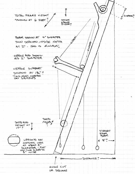
In all the 'artifact' samples, the two uprights have been flattened off on two sides. The supporting fork at the top of the uprights (for the top beam) are made of separate pieces, cut to shape and pinned into place. This is a significantly weaker construction method, as the load runs across the direction of the grain, and all the weight is entirely born by the two pins. A better method is to use two natural limb joints, where the grain will run around the fork and so is significantly stronger. The ideal way to attach these as separate pieces would be to set them into a large dovetail joint. (Readers will note that this is Evil Wood talk : 'I said I don't have much use for them, not that I don't know HOW to use them'.) In the end I decided to use one piece naturally forked limbs to ensure strength but reduce complexity.
The next concern was about materials, and how these might fit into our proposed scenario for DARC at Vinland. Initially it was suggested that 'Ka∂lin' would be a 'professional' weaver, and as such would likely have brought her loom with her on the immigration trip from Iceland. Karen, however, was a bit concerned that this story element might overplay her actual weaving skills. As a compromise, it was decided that the loom she would would work on at LAM would be one that could have been constructed at Vinland itself, perhaps skillfully built (?) but of available local materials. Birch was chosen, as it was available in both Iceland (still) and Vinland circa 1000 AD.

To that end, in mid March I wandered off into a local woodlot (where I have permission to cut). After three hours slogging around in mushy snow and melt water pools, I selected two standing birch trees to fell. This proved much harder than it might seem, I looked a dozens of trees through the swampy area. The key was finding two in the right size range (5 - 6 inch diameter) with naturally occurring forks in the correct configuration. Even cut down to an eight foot length, a six inch green log is damn heavy! I also gathered a standing but long dead (and dry) spruce sapling. This piece is dead straight, and tapers evenly from 3 1/3 inches at the base through to about 3/4 an inch - over a 23 foot length. I ended up making a second trip into the bush later to return to the cutting sites to gather smaller diameter forked branches to use for the shed supports and beam winding shafts.
The first step was removing all the bark. To keep the whole project looking as 'authentic as possible, this work was done using a hand axe. The smaller existing branches would be trimmed back to short lengths, providing a number of natural hooks for eventual hanging of weaving tools.
Special attention was given to the method of cutting the ends of the top beam. These ends would be clearly visible. So they were cut more or less flush by using the hand axe and a mallet. This does leave an entirely different finish than slicing off with a modern saw.
YouTube segment showing the preparation of the raw logs.
The images above show the majority of the loom's frame completed.
BELOW : The completed loom. You will see it has three positions for the lower shed support. There are a total of 4 positions for the heddle support rods. (You may notice this is the more standard layout, the two longer pole pieces for the Icelandic method will be made up later.)
 ≈
≈
With the living history presentation by DARC at L'Anse aux Meadows NHSC coming up this summer (August 16 - 25, 2010) the entire group is re-working a LOT of our equipments. Everyone in DARC is making a very special effort to make this presentation of the very highest standard. Our normal museum display focuses on a more 'urban' view, centred on the 'life of the craftsman'. The objects are typically chosen from a greater span of both geography and time. For the DARC at Vinland presentation, we are tightening up to 1000 - 1010 AD and to primarily Greenland and Iceland for our prototypes. (An ongoing discussion of how this effects our presentation can be found on the DARC blog.)
Textile production is a major element in DARC's combined skill set and physical presentations. This is especially the case for the story of LAM, where one of the signature artifacts was a small soapstone spindle whorl.
My concern is that the several warp weighted looms currently being used by various members of the group (at least four) are all too 'modern' in their construction details. (Beware: Textile jargon coming up!)
The historic prototypes:
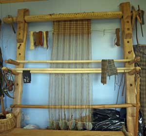 | 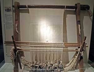 |  |
| Old Scatness, Scotland Likely 1800's? | National Museum of Iceland Perhaps 1700's? | Stong Farmstead, Iceland Modern reconstruction |
Images above by Karen Peterson
After considerable discussion, it was decided to build a new loom. The key was to not only consider the artifact prototypes available, but also the raw materials available on hand in both Iceland and Vinland circa 1000 AD. One primary problem in looking at the existing samples is that all of them are at best no older than the 1700's. Almost all have been heavily restored. A good number of those on display in museum collections are in fact modern replicas. Our own textile workers have been known to be puzzled by some of those on display. "Well, that just will not work!" is a repeated comment. (Few museum displays are actually set up by involved workers in the related skills, see any of my earlier comments on blacksmithing exhibits.)
The primary difference between the more 'continental' style and a distinctively 'Icelandic' style of loom appears to be in the difference in how the heddle bar is supported. (The heddle bar is the horizontal rod to which one set of the up and down warp threads are attached.) The more commonly used method in most re-constructions I have seen uses the form seen on the Old Scatness sample. That is a pair of forked branches or notched boards, which fit into a series of holes running along the uprights. This arrangement allows for adjusting the distance and position of the heddle rod, and thus controls the width of the shed (distance between front and back warp threads). This arrangement is physically quite strong, as the considerable force caused by supporting the loom weights will push straight back down the shed support rods and back into the frame.
On the Icelandic pattern, the heddle supports are two longer poles or planks, wedged between the floor and the lower horizontal line of the shed support. The advantage of this method is both ease of construction and that it is almost infinitely adjustable. The major problem is that now the force of the loom weights is directed in a diagonal line against the side of the shafts.
In truth, as the major elements of the frame of the loom are virtually identical, it was decided to design the new loom to allow it to be mounted up for either method. There would be the required holes drilled in the uprights and a set of forked shed supports, plus the longer and heavier rods included to set up for the Icelandic tradition.
In all the 'artifact' samples, the two uprights have been flattened off on two sides. The supporting fork at the top of the uprights (for the top beam) are made of separate pieces, cut to shape and pinned into place. This is a significantly weaker construction method, as the load runs across the direction of the grain, and all the weight is entirely born by the two pins. A better method is to use two natural limb joints, where the grain will run around the fork and so is significantly stronger. The ideal way to attach these as separate pieces would be to set them into a large dovetail joint. (Readers will note that this is Evil Wood talk : 'I said I don't have much use for them, not that I don't know HOW to use them'.) In the end I decided to use one piece naturally forked limbs to ensure strength but reduce complexity.
The next concern was about materials, and how these might fit into our proposed scenario for DARC at Vinland. Initially it was suggested that 'Ka∂lin' would be a 'professional' weaver, and as such would likely have brought her loom with her on the immigration trip from Iceland. Karen, however, was a bit concerned that this story element might overplay her actual weaving skills. As a compromise, it was decided that the loom she would would work on at LAM would be one that could have been constructed at Vinland itself, perhaps skillfully built (?) but of available local materials. Birch was chosen, as it was available in both Iceland (still) and Vinland circa 1000 AD.
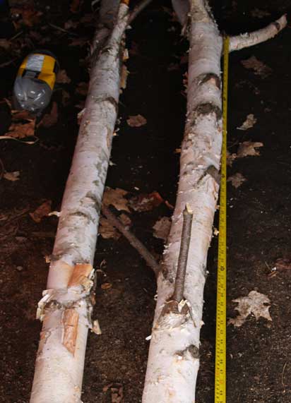
To that end, in mid March I wandered off into a local woodlot (where I have permission to cut). After three hours slogging around in mushy snow and melt water pools, I selected two standing birch trees to fell. This proved much harder than it might seem, I looked a dozens of trees through the swampy area. The key was finding two in the right size range (5 - 6 inch diameter) with naturally occurring forks in the correct configuration. Even cut down to an eight foot length, a six inch green log is damn heavy! I also gathered a standing but long dead (and dry) spruce sapling. This piece is dead straight, and tapers evenly from 3 1/3 inches at the base through to about 3/4 an inch - over a 23 foot length. I ended up making a second trip into the bush later to return to the cutting sites to gather smaller diameter forked branches to use for the shed supports and beam winding shafts.
The first step was removing all the bark. To keep the whole project looking as 'authentic as possible, this work was done using a hand axe. The smaller existing branches would be trimmed back to short lengths, providing a number of natural hooks for eventual hanging of weaving tools.
Special attention was given to the method of cutting the ends of the top beam. These ends would be clearly visible. So they were cut more or less flush by using the hand axe and a mallet. This does leave an entirely different finish than slicing off with a modern saw.
YouTube segment showing the preparation of the raw logs.
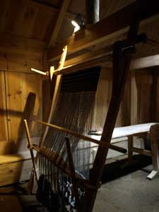
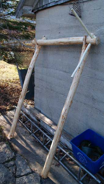 | 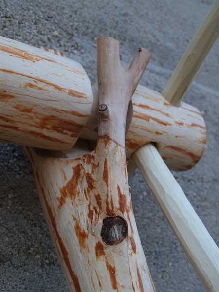 |
| Frame under construction | Detail of beam and upright |
The images above show the majority of the loom's frame completed.
BELOW : The completed loom. You will see it has three positions for the lower shed support. There are a total of 4 positions for the heddle support rods. (You may notice this is the more standard layout, the two longer pole pieces for the Icelandic method will be made up later.)
≈
Friday, April 02, 2010
Subscribe to:
Posts (Atom)


