Chris Jordan
I had this passed to me by one of the other members of An Droichead:
Running the Numbers
An American Self-Portrait
" This series looks at contemporary American culture through the austere lens of statistics. Each image portrays a specific quantity of something: fifteen million sheets of office paper (five minutes of paper use); 106,000 aluminum cans (thirty seconds of can consumption) and so on. My hope is that images representing these quantities might have a different effect than the raw numbers alone, such as we find daily in articles and books. "
Take a look - especially consider the scale of the images. I normally find a lot of this kind of concept work more annoying than in any way valuable. Jordan is however an extremely skilled and keen eyed photographer. He is bringing that eye to these commentaries on environment and conspicuous consumption in America.
Tuesday, January 29, 2008
Monday, January 28, 2008
Bellows Reonstruction 3

The image is loading directly from its internet source - the University of Pittsburgh.
http://www.pitt.edu/~dash/sigurddoor.html
http://www.pitt.edu/~dash/sigurdstone.html
Both by Professor D. L. Ashliman of the University of Pittsburgh
The core members of the DARC smelt team (Neil, Kevin, Dave and Ken) where up over the past weekend. We discussed what we are learning, what we have done, and what direction this year's campaign at the smelter should take.
The main thrust will be work towards the reconstruction of the Icelandic grass sod smelter. At present we have to pieces of technical work to refine. The first (not dealt with there) is the creation of a workable bog ore analog. The second is to finally get an effective bellows design.
Considerable background help on this has come from Jens Jørgen, who works at the living history side of the Heltborg Museum in NW Denmark.
Unfortunately the museum web site does not seem to detail the iron age farmstead reconstruction where Jens works as blacksmith and also smelts iron.
He has posted up a number of images related to the iron demonstrations and his bellows specifically.
There is one primary reason why the current bellows reconstruction (detailed over the last couple of postings here) does not work as expected when applied to an iron smelting furnace. The actual air volume produced is significantly less than the projected theoretical volume. (It should be noted that this bellows design and construction has proved very effective for blacksmith's forges and for bronze casting.)
Neil has pointed out that even small changes in the measurements can produce large variations in potential air. Using the new set of measurements from the bellows directly and he crunched the numbers. The highest possible *theoretical* volume produceable by my reconstruction is in the range of 500 - 600 LpM. So with the * actual * measured volumes at closer to 150 - 200 LpM - what the heck is going on?
So I did what I should have done at the start of this - I dragged the bellows out and set it up inside my (heated) studio. I pumped and measured and took photographs. I looked and pumped and measured some more. Then I thought about it and looked again.
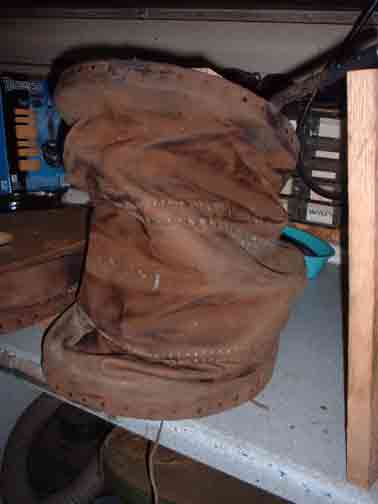
When I had initially made the reconstruction blueprints, I had tried some body positions for the operator - just faking it. I based things like handle positions and most importantly - the amount of lift - based on that. This suggested to me that the maximum extension of the top plate could be 46 cm. I cut the fullness of the leather bags to allow for that elevation. There are three lens shaped pieces to the bag, each about 15 cm at the widest point.
In actual use however - what the operator * really * does is raise that plate to only 30 cm (less when the bellows is mounted at waist height on a forge table). The net effect is that one complete leather section is not being used. Since there is more bag that required, the whole bag collapses sideways and crumples - effectively reducing the amount of air inside. On the exhaust stroke - that extra leather has to be compressed - and so the plate can not be depressed as far as it might be with a loss of volume again.
My only excuse here is that I'm usually the one on the bellows - or have my head stuck inside the smelter - or trying to organize a 3 - 6 person team - or running back and forth to the workshop trying to find tools...
The operator of the bellows can't actually SEE this folding and distortion of the bag. Its only really obvious from just behind and at the same eye level as the bellows. As an uninvolved observer. We also gave up on use of the small bellows after I met Lee and Skip the first time and they told us about the correct use of higher air volumes.
On top of that, I think the leather I used may also be a bit heavier than required. (At the time I had access to a large amount at a good price.) There are wire stiffeners along the double seam lines - but these would be better replaced with metal rod hoops (like 1/4 round rod).
1) Neil has ordered a copy of the small blacksmith's bellows for his glass bead furnace project. This will be made up using the current physical measurements, but with two important changes.
- First the bag will be cut with only two leather lames - giving a maximum loft in use of 30 cm. This will reduce the folding of what is just unused leather surface. The wooden frame will be made up, and then a fast test bag will be made up out of taped plastic. This should allow for a fast test series to be made to measure the air volume with the shorter bag.
- If this test proves effective, then the bags will be made up using a lighter (likely deer skin) leather than has been used on previous versions.
- The centre seam will be fitted with a more rigid metal hoop than has been used in the past (at least 3/16 if not 1/4 inch round steel rod).
Taken together, this new unit should allow us to record more accurate numbers for the possible use of the historic patterned bellows in smelting.
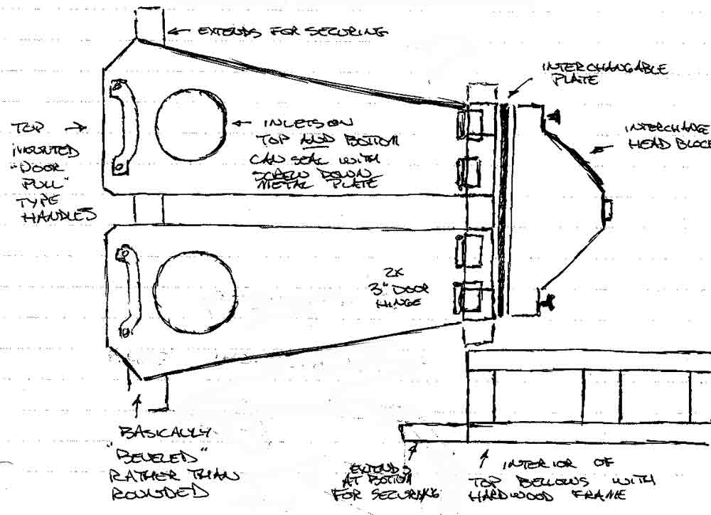
2) A second 'test bed' bellows will be made up (as seen in the illustration above).
- Measurements for this bellows will be determined by taking a theoretical model which is able to produce roughly 1500 LpM. The desired working air volume is actually 1000 LpM. Numbers and images from Jens suggests a true working efficiency of about 2/3 theoretical is likely (assuming good design). Working from more theoretical and experience proven volume requirements, our current run of furnaces work best at roughly 500 to 800 LpM.
- The sides of the bellows will be flat surfaces. This allows to hold the bags in place with metal strips held with screws. This permits easy modifications to the interior of the bag and plates if required.
- The bellows plates will be cut and fitted with intake holes on both top and bottom. In use, either side can be sealed using a metal cover again screwed into place. In this way the difference between top and bottom mounted air valves can be compared. Physical mounting systems for the bellows, and how this relates to operator strain can be compared. An extension of this is further recording of the related debris fields.
- The distance at hinge point of the bellows will be greatly increased, at least double the current measurement. This will allow the installation of two door type hinges on each plate, greatly improving durability.
- The head block of the bellows is a simple boxed shape. To this can be screwed a removable, even interchangeable, exhaust unit. Different types of valves, port shapes and tube diameters can then be attached to measure their impact on flow.
- The handle for the operator will be a wide wooden D type. This will be mounted directly in line with the bellows hinge axis.
Most of the tests involved are primarily static tests, or short applications of human power to the existing air pipe system. There was more interest than I expected in conducting a full smelt using a proven bellows for air. With a proven smelt (bloom production) DARC will have a certain 'all Norse' demonstration possible.
Darrell
(As always, thanks to Skip Williams, who always tells me when I'm 'pissin in the wind' - think Neil Young)
Saturday, January 26, 2008
Last week...
• The Ghost of Christmas Present: Oh, what is this Frank? Oh, oh, look Frank. It's a toaster.
[hits him in the forehead with the toaster]
• Frank Cross: The bitch hit me with a toaster.
• Ghost of Christmas Present: Sometimes you have to *slap* them in the face just to get their attention!
thanks to Vandy
[hits him in the forehead with the toaster]
• Frank Cross: The bitch hit me with a toaster.
• Ghost of Christmas Present: Sometimes you have to *slap* them in the face just to get their attention!
thanks to Vandy
Friday, January 25, 2008
Bellows Reconstruction 2
I have been working over the reconstructed blacksmith's bellows we have been attempting to use for our iron smelting experiments. Or perhaps its safer to say 'have been distorting my ideas around Viking Age iron smelting methods'.
This may prove to be a bit of a repeat to long time readers, but I wanted to get my (derailed) train of thought recorded. I have been obsessed with this whole thing for a week now.
ONE - Were DID those measurements come from?
These are are the only two historic references available to us for what a bellows looks like in the Viking Age. There is not a single surviving artifact (that I have seen or ever heard of). Please assume that I do understand all the problems associated with taking an artist's illustration and attempting to use that for a reconstruction.
The first illustration is a side view in action and gives us a human hand (at 10 cm) to use for size estimates. (Yes I know the illustration also suggests swords are 10 cm wide and heads are the size of beach balls.)
- The working loft (raising the plate) is seen as huge - actually over 90 degrees. You do see that one side is already at maximum when the other is still being exhausted. It turns out that is actually how you correctly move the plates to produce a steady flow of air.
- It shows the operator not actually using any kind of handle, but gripping the edge of the top plate. Again we found this is exactly what many operators will end up doing in action.
- It shows each of the bags composed of each three separate lame sections. These are strengthened somehow so they do not deform under working pressure (either thick seems or some internal bracing).
- a very rough length can be established for the bellows, roughly four or five hand widths (40 - 50 cm). Although the image may be a bit shortened horizontally, the bellows tubes are shown as very long - there would be room for the artist to extend the length of the bellows if he had desired.
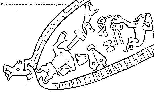
The second illustration is more of a diagram, top down, with no figure directly associated to it. It might be possible to associate hand size - but given the figure proportions and related to the hammer scale, this is less likely.
- The relationship of length to width is roughly 2.5 to 1. Considering the length from the first illustration, that suggests a width in the range of 20 cm for each plate.
- The end of the bellows plate that attaches to the head block (where the hinges are) is seen to be very narrow. Applying the scale, it is in the range of 5 cm.
- The ratio between the the top mounted air intake and the width of a bellows plate is roughly 1:3, suggesting a hole size of about 7 cm.
One last piece of important data is the probable size of any outlet tubes. Using the first illustration, the suggestion is about 5 cm. There is however clear artifact evidence here. Ceramic tuyeres from a number of furnace types are relatively common, and most fall clearly into a size of about 2.5 cm internal diameter. Several bellows stones have been found, these too fall into that roughly 2.5 cm measurement.
The Reconstruction
- The numbers above are measured directly off the bellows (instead of off my blueprints as earlier ones were)
- The 30 cm loft is the working measurement with an operator kneeling and bellows placed on the ground. With the bellows set on a table (like at a raised forge) the working loft drops to about 25 cm.
- When calculating potential air volumes, remember that the loft measurements are on the outside of the wooden plates. The plates themselves are a total of 5 cm thick. The chamber measurement is thus 25 and 20 cm.
There are no valves on the outlet end. Significant air is prevented from being drawn back up the exhaust tube by two factors:
- First the ratio between the inlet and outlet valves. In operation the leather disk that serves as the inlet valve is secured at two points across its mid line. In effect only part of the entire 10 cm space is opened, but virtually no air is pulled back up the exhaust port.
- There is one exhaust port for each chamber, with two pipes leading to a leather box. The box forms the coupling to the single pipe leading to the tuyere. In action this Y shaped arrangement creates a blast effect forward, further limiting the ability of air to be withdrawn back up the opposite exhaust tube. The leather also serves as a flexible coupling, reducing the vibration from bellows operation from reaching the attached tuyere.
More to come on this topic...
There are earlier postings discussing this specific reconstruction:
http://www.blogger.com/img/gl.link.gif2007_07_22_archive.html
http://www.blogger.com/img/gl.link.gif2007_10_28_archive.html
This may prove to be a bit of a repeat to long time readers, but I wanted to get my (derailed) train of thought recorded. I have been obsessed with this whole thing for a week now.
ONE - Were DID those measurements come from?
 |  |
Hyllestad Church CarvingCarving | Ramsund Rune Stone |
These are are the only two historic references available to us for what a bellows looks like in the Viking Age. There is not a single surviving artifact (that I have seen or ever heard of). Please assume that I do understand all the problems associated with taking an artist's illustration and attempting to use that for a reconstruction.
The first illustration is a side view in action and gives us a human hand (at 10 cm) to use for size estimates. (Yes I know the illustration also suggests swords are 10 cm wide and heads are the size of beach balls.)
- The working loft (raising the plate) is seen as huge - actually over 90 degrees. You do see that one side is already at maximum when the other is still being exhausted. It turns out that is actually how you correctly move the plates to produce a steady flow of air.
- It shows the operator not actually using any kind of handle, but gripping the edge of the top plate. Again we found this is exactly what many operators will end up doing in action.
- It shows each of the bags composed of each three separate lame sections. These are strengthened somehow so they do not deform under working pressure (either thick seems or some internal bracing).
- a very rough length can be established for the bellows, roughly four or five hand widths (40 - 50 cm). Although the image may be a bit shortened horizontally, the bellows tubes are shown as very long - there would be room for the artist to extend the length of the bellows if he had desired.
The second illustration is more of a diagram, top down, with no figure directly associated to it. It might be possible to associate hand size - but given the figure proportions and related to the hammer scale, this is less likely.
- The relationship of length to width is roughly 2.5 to 1. Considering the length from the first illustration, that suggests a width in the range of 20 cm for each plate.
- The end of the bellows plate that attaches to the head block (where the hinges are) is seen to be very narrow. Applying the scale, it is in the range of 5 cm.
- The ratio between the the top mounted air intake and the width of a bellows plate is roughly 1:3, suggesting a hole size of about 7 cm.
One last piece of important data is the probable size of any outlet tubes. Using the first illustration, the suggestion is about 5 cm. There is however clear artifact evidence here. Ceramic tuyeres from a number of furnace types are relatively common, and most fall clearly into a size of about 2.5 cm internal diameter. Several bellows stones have been found, these too fall into that roughly 2.5 cm measurement.
The Reconstruction
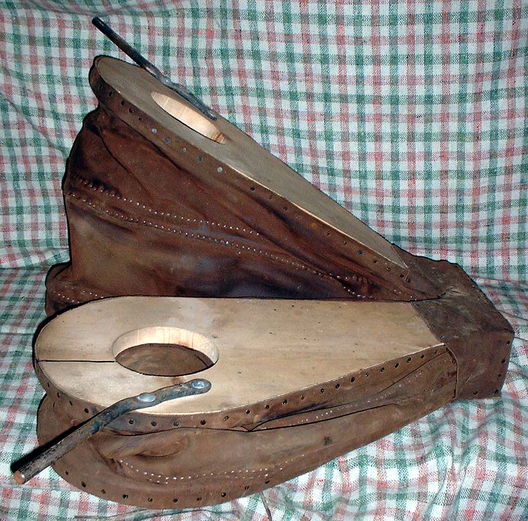 | Reconstructed Norse Blacksmith's Bellows The rough dimensions of the reconstruction are: total length - includes head block: 70 cm total width: 58 cm individual bag length: 50 cm individual bag width: 25 cm individual plate width at head block: 8 cm maximum loft height: 45 working loft height: 30 cm interior of bag at loft: 25 cm inlet valve size; 10 cm outlet tube size: 2 cm minimum internal diameter Photographed against a 1 cm grid |
- The numbers above are measured directly off the bellows (instead of off my blueprints as earlier ones were)
- The 30 cm loft is the working measurement with an operator kneeling and bellows placed on the ground. With the bellows set on a table (like at a raised forge) the working loft drops to about 25 cm.
- When calculating potential air volumes, remember that the loft measurements are on the outside of the wooden plates. The plates themselves are a total of 5 cm thick. The chamber measurement is thus 25 and 20 cm.
There are no valves on the outlet end. Significant air is prevented from being drawn back up the exhaust tube by two factors:
- First the ratio between the inlet and outlet valves. In operation the leather disk that serves as the inlet valve is secured at two points across its mid line. In effect only part of the entire 10 cm space is opened, but virtually no air is pulled back up the exhaust port.
- There is one exhaust port for each chamber, with two pipes leading to a leather box. The box forms the coupling to the single pipe leading to the tuyere. In action this Y shaped arrangement creates a blast effect forward, further limiting the ability of air to be withdrawn back up the opposite exhaust tube. The leather also serves as a flexible coupling, reducing the vibration from bellows operation from reaching the attached tuyere.
More to come on this topic...
There are earlier postings discussing this specific reconstruction:
http://www.blogger.com/img/gl.link.gif2007_07_22_archive.html
http://www.blogger.com/img/gl.link.gif2007_10_28_archive.html
Thursday, January 24, 2008
Testing Dark Ages AIR
For those of you who are members of Early Iron, you know that the last week I have sent in a couple of detailed postings related to the two major problems that continue to plague the ongoing experimental smelts: lack of consistent ore & Dark Ages air systems.
A lot has been built on my own problems getting a suitable working bellows system that conforms to the specific historic period of my interest. Thats specifically Northern Europe, and limited to the period between roughly 450 and 1100.
Roman smelters are much larger than those used after the end of direct Roman occupation in the regions after 450. These designs often employ tall enough stacks (over 1.5 metres) that allow for passive air drawn. Even though mostly only the bases remain, use of multiple tuyeres places around the diameters suggests this method.
Drum bellows (or cask bellows) are simple cylinders with a wooden cover holding an intake valve, with a second exhaust valve at the base. Again a good working system, but much earlier than my specific time frame. (At the risk of over simplifying - you can consider these 'Celtic Iron Age')
On the other end of the time chain are those manuscript representations from the Medieval period propper. In illustrations from the 1300 - 1500's you will see both the later 'great bellows' (two stacked chambers) and the earlier 'double bellows' (two separate chambers) types. The double bellows systems are normally shown either as large units attached to water wheels or smaller units operated (not entirely clear in depictions) using some kind of lever system at the blacksmith's forge.
Once again, all the evidence dwindles away at about 1200. All we have for the roughly 600 years before the Crusades are those two Viking Age illustrations of (admittedly and problematicly) blacksmith's bellows.
You can check an earlier posting (October 30, 2007 - Bellows Test ) for a look at the primary reference, that carved on the church at the Hyllestad Church in Norway. The second illustration is more cartoon like, but is a top down view that gives some idea of width to length and relative proportion of the upper inlet hole.
I'll leave you today with a look at that second illustration, from a large carved stone at Ramsund, Sodermanland, Sweden.
Monday, January 14, 2008
On Tylecote - 'A little Learning...
...is a dangerous thing.'
 The first image is from R.F. Tylecote's 'The Early History of Metallurgy in Europe' (pg 155 - Longman Group, Essex England, 1987) it is captioned 'after Tylcote et al. 1971' That second citation for that paper I don't have.
First thing - with more research five years ago, I might have stumbled on this illustration. Unfortunately it is not further detailed in the text. It does show a smelter in the size range of what my team has been working with. Most significantly, the height above the tuyere is clearly marked at 50 cm. The other measurements can be estimated from that - and give an internal diameter of about 30 cm. A good working location for the tuyere above the base of the furnace can be estimated at about 15 cm. In practice we have found (through many trials and errors!) that all these measurements are critical.

The main thing different from the Tylecote illustration and my own working drawing is the angle of the tuyere. Now we have found this to be critical as well, inside the overall system we are currently using. To keep the tuyere from being drowned in liquid slag, there needs to be a downwards angle to the air blast, not horizontal as seen in Tylecote's. Tylecote is also clearly illustrating the situation inside a furnace operating with LOWER AIR VOLUMES. The distance of penetration of the combustion area shows that.

One part of the illustration I do quibble about is that there is a clear empty space shown under the slag bowl. At the start of the smelt sequence, this space would be filled with charcoal of course. It the illustration is presumed to be the situation at the point slag is being tapped, then the lower material would have been cleared as shown. Most importantly, the original illustration does not correctly show the bloom. What is shown is actually the position of the entire slag bowl, and of course the bloom develops at the upper front within the slag bowl. One last difference between Tylecote's drawing and what we have directly observed is the indicated extent of 'fluxed lining'. In actual fact, this distinctive glazing of the inside surface of the smelter does not extend past the bottom of the slag bowl as he showed. It does however extend for some distance above the tuyere.
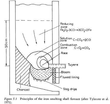 The first image is from R.F. Tylecote's 'The Early History of Metallurgy in Europe' (pg 155 - Longman Group, Essex England, 1987) it is captioned 'after Tylcote et al. 1971' That second citation for that paper I don't have.
First thing - with more research five years ago, I might have stumbled on this illustration. Unfortunately it is not further detailed in the text. It does show a smelter in the size range of what my team has been working with. Most significantly, the height above the tuyere is clearly marked at 50 cm. The other measurements can be estimated from that - and give an internal diameter of about 30 cm. A good working location for the tuyere above the base of the furnace can be estimated at about 15 cm. In practice we have found (through many trials and errors!) that all these measurements are critical.
The main thing different from the Tylecote illustration and my own working drawing is the angle of the tuyere. Now we have found this to be critical as well, inside the overall system we are currently using. To keep the tuyere from being drowned in liquid slag, there needs to be a downwards angle to the air blast, not horizontal as seen in Tylecote's. Tylecote is also clearly illustrating the situation inside a furnace operating with LOWER AIR VOLUMES. The distance of penetration of the combustion area shows that.
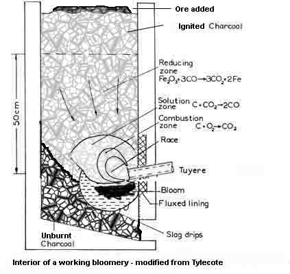
One part of the illustration I do quibble about is that there is a clear empty space shown under the slag bowl. At the start of the smelt sequence, this space would be filled with charcoal of course. It the illustration is presumed to be the situation at the point slag is being tapped, then the lower material would have been cleared as shown. Most importantly, the original illustration does not correctly show the bloom. What is shown is actually the position of the entire slag bowl, and of course the bloom develops at the upper front within the slag bowl. One last difference between Tylecote's drawing and what we have directly observed is the indicated extent of 'fluxed lining'. In actual fact, this distinctive glazing of the inside surface of the smelter does not extend past the bottom of the slag bowl as he showed. It does however extend for some distance above the tuyere.
Saturday, January 12, 2008
Impact of Viking Age Weapons
This is a more general commentary, and may already be well known to my readers. I had taken the time for a measured reply to the inquiry, so figured it would fill todays submission to Hammered Out Bits...
Nick wrote:
>I would be very interested to hear your thoughts about Viking metals
>technology vs those employed by other societies at the time. The series
>has a heavy science focus, and we would like to compare the strength and
>durability of Viking metals with those of opponents they faced. There
>may well have been little difference (in which case we will not
>concentrate on this) but we feel that our viewers would be very
>interested in the intricacies of how Vikings welded as well as wielded
>their weapons.
There are a couple of factors that lead to 'the Vikings' having the reputation that they did historically.
The largest one is a cultural / environmental aspect. The rugged geography of Scandinavia was harsh, it bred strong people. Most Norse lived in widely separated extended family farmsteads. This gave a rugged individualism with close ties to kin and band. Farming was herding, which means a high protein diet - which leads to increased body size. In a world where strength and length of arm were critical in combat, the Norse were just simply bigger and tougher.
That geography also shaped religion and world view. To the Norse the powers were big, aloof, and unknowable. All a person could do was struggle and hope to survive. Even the gods would go to their destruction in the final battle at worlds end, so what could mere men expect? They also were the last pagans in a Europe fully turned Christian.
The single greatest weapon in the arsenal of the Vikings was the longship. The geography of rugged mountain interiors surrounded by coastlines often cut by fjords and bracketed by islands directed people to the sea. The longship was composed of flexible planks, clinker built and pegged and riveted to each other - rather than nailed to a rigid frame. The graceful curves of the hull rode up over the waves, with a long keel allowing for tacking against the wind. Drawing hardly any water even fully loaded, the warships could be rowed as well as sailed. Combined with the sophisticated technology of the longhip was a well developed set of navigation skills. Only the Norse could tell their relative position out of site of land.
One weapon favoured by the Vikings (especially the Danes) had not been largely absent on the battlefield for a long time. This was the axe. Ranging from lighter throwing axes to two handed battle axes, these weapons can be devastating in combat. Modern conceptions of weight and size are totally incorrect. A single hand axe (balanced by a left hand shield) would range one kilo or less. Even a two handed axe on a one metre haft would rarely mass more than two kilos. An axe has huge destructive impact when swung with two hands - but it also has hardly any defensive capability. Truly a weapon for the fearless, the Berserk.
The methods of smelting iron were similar throughout Europe during the period from the end of the Roman era to about the times of the Crusades. Mostly iron rich bog ore was smelted in simple flask shaped furnaces into metal blooms of wrought iron. Source ore could differ considerably (why some areas developed better reputations for quality ironwork) and generally the ore available in Scandinavia was of high quality. Wrought iron forges well under the hammer, but is a relatively soft material. It will bend rather than break when stressed, but is not hard enough to hold a cutting edge. By selecting (or creating) iron with a higher carbon content, the result was a type of steel. This metal can be treated to make it hard enough to stay sharp, but at the cost of becoming brittle and prone to shatter. The 'bladesmith's dilemma' is how to balance the requirements of a long cutting edge against the basic restrictions of the metals available a the time. An ideal sword needs to hold its edge in use, but also needs to be flexible enough to absorb the shock of combat. The simplest solution to this dilemma is to weld a piece of hard steel on to a core of softer iron, a technique developed by blade makers all over the world. In the North, this basic principle was further refined to create some of the most complex forged objects ever seen.
In terms of metallurgy, the one significant technology originally developed by the Saxons, and widely employed by the Norse was the technique of PATTERN WELDING. A pile of alternating hard and soft plates were forge welded into a solid block of many layers. Several of these blocks were then drawn out to thin rods. The rods were then twisted, alternating right and left hand twists, sometimes in complex sequences. The carefully prepared rods were then forge welded down their long lengths to create the core section of a blade. The effect of this layered and twisted core was like laying a series of coil springs down the centre of the sword - it would flex under strain but snap back to true without damage. To this prepared core (sometimes composed of as many as 8 twisted rods) would be next welded a cutting edge. These edge pieces may have been a single hard steel, or might themselves be composed of blocks stacked, welded, folded and welded again to create many layers. The final welded blank would then be forged to shape, laboriously polished and finished with a functional cross hilt.
Such blades were the work of master craftsmen, often of royal caliber. They bore names, and became heirloom objects. A sword might have a larger legend than the man who carried it.
Monday, January 07, 2008
2008 Courses?
The following are the tentative dates for the 2008 courses offered at the Wareham Forge:
Basic Blacksmithing
May 9 / 10 / 11
June 20/ 21 / 22
July 25 / 26 / 27
September 26 / 27 / 28
October 24 / 25 / 26
Introduction to Smelting Iron
June 6 / 7
Intermediate / Special Interest Courses
For the following courses, the exact course content on a specific date will vary depending on student enrollment.
July 5 / 6
May be one of:
Basic Bladesmithing
Intermediate Blacksmithing
Basics of Metal Casting
October 18 / 19
May be one of:
Basic Bladesmithing
Intermediate Blacksmithing
Introduction to Layered Steels
Saturday, January 05, 2008
Modern Skills applied to Ancient Craft?
Right now the Artisan Blacksmith Association of North America (ABANA) is going through some problems. From my vantage point, I see this as:
- too much cost against too little value
- too much stress on schmoozing
- remote and extremely costly annual events with limited direct education
- stress on demonstrators with fame - but little communications skills
I only ever was a paid member one year (1990) and that mainly so I could attend the conference that year - held in Alfred NY (near Rochester). My final cost for the four days was about $500, and I got very little value against that expense. (I would have gained more by using the money for a week at the Campbell Folk School, or spending it on books.)
Right now ABANA is seeking directions via an on line opinion poll. You don't have to be a member to submit. If you work in forged metals you might consider adding your comments
HERE
One of the thing that has plagued ABANA (in my opinion) is that it is basically a self enrolled special interest group. Many of those most active in setting the conduct of the organization are actually not skilled or active as actual blacksmiths. You pay your money - you get membership. Balanced against this is an often artificial measure of what constitutes skill. It is so often not based on past work - but dominated by modern machine process. (The Ontario Government has been looking at some kind of definition to 'Artisan Blacksmith'. I've seen the prototype skills requirements, and they include knowledge of plasma cutters and CNC machines!)
For your interest - here is what ABANA posts as the required skills for a basic level journeyman blacksmith:
SKILLS EXPECTED FOR THE EMPLOYMENT OF A JOURNEYMAN
Blacksmithing Standards developed by the Appalachian Blacksmiths Association, an ABANA Affiliate, and registered with the Bureau of Apprenticeship and Training, United States Department of Labor.
1. Drawing Out: Draw a bar to a point or dress an edge or point a tool.
2. Upsetting: Upset to at least 1-1/2 times the diameter or width of a bar on the end and in the middle.
3. Bending: Make a ring out of bar stock or flat stock; forge a square corner right angle bend in square stock.
4. Drifting: Make a drift and use it to smooth, shape or enlarge a hole.
6. Mortise and Tenon: Make an assembly from at least two separate pieces using this technique.
7. Collaring: Make an assembly from at least two separate pieces using this technique.
8. Scroll Work: Make two different types of scrolls.
9. Splitting: Split a bar with a hot cut in the middle or at the end of the bar.
10. Fullering, Grooving, Veining, Set Hammering: Show examples of each or if used as an intermediate technique, describe how and why the techniques are used.
11. Riveting: Make two assemblies from at least two separate pieces for eachassembly using hot riveting and cold riveting (pop riveting is not acceptable).
12. Forge Welding: Show at least three different techniques.
13. Arc Welding, Brazing, Soldering, Oxyacetylene Torch Welding: Show an example of each.
14. Hot Rasping, Filing: Hot rasp the torch cut end of a bar to reasonable straightness and evenness; show a workpiece which has been filed to a smooth, flat surface; describe the types, care and use of files.
15. Sinking, Raising, Metal Spinning: Make or show a hemispherical or hollow object made from flat sheetusing any one technique.
16. Grinding: Know how to use a body grinder (portable grinder), pedestal grinder, belt grinder, sharpening stones and abrasive papers; know the types of abrasives and how they are graded and classified; show an edge tool that you have sharpened.
17. Drilling, Tapping, Die Work and Threads: Drill and tap a hole, thread the end of a bar with a die; know the common thread classifications; know the common drill size classifications and the care and use of twist drills.
18. Heat Treating, Hardening, Tempering, Annealing, Case Hardening: Know how to properly anneal, harden and temper carbon tool steel; know how to case harden mild steel, know the colors for tempering; make or show a tool you have made that has been heat treated that will cut or forge mild steel without breaking or deformation on the working end.
19. Heading: Head two bolts, one square headed and one hex headed; head a nail; head a rivet.
20. Cutting and Shearing: Know how to use the hot cut, cold cut, hacksaw, tinsnips, bench or floor shear; know how to use the oxyacetylene torch for cutting and demonstrate each technique.
21. Swaging: Swage a tenon or make the end of a square bar round using a swage.
22. Twisting: Show two different twists in a square bar.
23. Shop Safety: Know first aid techniques for cuts, burns, abrasion and other shop related injuries; describe methods of hearing, sight and body protection and why they are necessary; know power tool and machinery safety including welding equipment safety.
24. Basic Metallurgy: Know the properties and use of wrought iron, mild steel, carbon and tool steels and their classifications, cast-iron, brass, copper, aluminum; know sheet and plate gauging for ferrous and non-ferrous metals.
25. Fire and Fuel: Know the constituents of good shop coal; know the different types of coal fires and fire maintenance.
26. Jigs and Dies: Make both a jig and a die for doing repetitive production work and show examples of work produced with them.
Friday, January 04, 2008
Bellows and Nails ??
Related to a question about avoiding or reducing the number of nails used to construct a Viking Age bellows. This a reasonable consideration, given the relative cost of metal and effort / production problems making small nails in the time period.
First take a look at the construction (mind you not TOO close!) on this bellows:

For this first version of a VA bellows, I used strips of willow, split from green wood, then soaked, bend to shape and nailed. The Wood bands are really what holds the leather tight to the planks. Fewer nails are required. (The ones you see there are the 'hand wrought head' style ones from Tremount - I did not make them.) Larger nails possed real problems with potentially splitting the wood. I did use a modern silicon caulking material to air seal the leather. Historically a hide or other organic glue would have been used. This substitution was made because I knew the bellows would be stored and used in quite damp conditions (at L'Anse aux Meadows NHSC).
What my latter versions used was smaller (and a lot more) regular carpet tacks. There are not any existing carpet tacks from the VA of course. What I have seen is only 'close' - related to the Sutton Hoo Burial (Saxon, circa 625 AD). In the construction of the lyre, small triangle shapes of copper are used as tacks to hold the top plate to the frame. It would be possible to make small tacks by starting by forging a strip of iron. Then triangular wedge shapes could be cut with a straight chisel. To hold leather (or a thin strip of wood) you would need some kind of spread out head to the tack. If you had previously made the right size and shape heading tool (punch a correct shaped hole into a thicker bar) you could likely do the heading cold. Please note that I have never come across any such tacks in the artifact record (But as Bruce says "absence of evidence is not evidence of absence").
From a design stand point, there are a couple of things wrong with the mark one bellows (first image):
- One is the proportion of intake to outlet holes. Further experimentation showed that better results were achieved with a larger intake - something like a ratio of 4:1. With a standard outlet tube size (determined by examining artifact tuyeres) at around 2.5 cm interior, that puts your inlet hole at about 10 cm diameter. This works well with a simple leather flap valve (a circle held at two opposing sides).
- It proved completely ineffective and unnecessary to have any kind of valve on the down stream side. The simple leather tab valves seen in the image above where latter pulled out. With a correctly designed Y tube and the proper proportion of inlet to outlet, plus the correct operator technique (!), no downstream valve is required.
- Although the small tab style handles are suggested by the only clear historic depiction of a blacksmiths bellows in operation (see bellow), it proved a quite ineffective style. Not surprisingly, most users ended up gripping the side of the top plate - just as seen in the source illustration.
- the hinges here are heavy leather backed up with two strips of wood. I owe Kevin from DARC the inspiration on this, as his first bellows (made for metal casting) used two nailed down metal plates to re-enforce leather as hinges.

Shows a latter reconstruction. This basic pattern has become my working standard. There are a number of these out there in various displays and working demonstration use. That image also shows the correct set up of a VA ground forge with bellows stone and flexible coupling leather Y tube.

Is the main historic reference for any kind of bellows from the Viking Age. It is dated closer to 1150 and from the Hyllestad Church in Norway. There is a second carving - a top down view on a rune stone from Ramsund Sweden - but is more cartoon like and not directly associated with a human figure (no way to get measurements).
I have made a fair effort in trying to track down any actual physical remains of a bellows from the Viking Age (or anything before about 1200.) So far I have not found reference to a SINGLE artifact. What we have is only the two carved images above. Every time I hear about a bellows, it turns out to be a late medieval (or later) unit found inside a site with a much longer occupation history.
** If ANYONE has any hard evidence of an artifact bellows from the Viking Age - PLEASE send me an image or a publication reference!! **
What we do know is that larger and more prosperous farm steads from the VA often have special built small workshops with evidence of a forge within them. There is of course no way to prove if a bellows and anvil were owned by the farm - or supplied by traveling blacksmiths on a seasonal visit.
First take a look at the construction (mind you not TOO close!) on this bellows:

For this first version of a VA bellows, I used strips of willow, split from green wood, then soaked, bend to shape and nailed. The Wood bands are really what holds the leather tight to the planks. Fewer nails are required. (The ones you see there are the 'hand wrought head' style ones from Tremount - I did not make them.) Larger nails possed real problems with potentially splitting the wood. I did use a modern silicon caulking material to air seal the leather. Historically a hide or other organic glue would have been used. This substitution was made because I knew the bellows would be stored and used in quite damp conditions (at L'Anse aux Meadows NHSC).
What my latter versions used was smaller (and a lot more) regular carpet tacks. There are not any existing carpet tacks from the VA of course. What I have seen is only 'close' - related to the Sutton Hoo Burial (Saxon, circa 625 AD). In the construction of the lyre, small triangle shapes of copper are used as tacks to hold the top plate to the frame. It would be possible to make small tacks by starting by forging a strip of iron. Then triangular wedge shapes could be cut with a straight chisel. To hold leather (or a thin strip of wood) you would need some kind of spread out head to the tack. If you had previously made the right size and shape heading tool (punch a correct shaped hole into a thicker bar) you could likely do the heading cold. Please note that I have never come across any such tacks in the artifact record (But as Bruce says "absence of evidence is not evidence of absence").
From a design stand point, there are a couple of things wrong with the mark one bellows (first image):
- One is the proportion of intake to outlet holes. Further experimentation showed that better results were achieved with a larger intake - something like a ratio of 4:1. With a standard outlet tube size (determined by examining artifact tuyeres) at around 2.5 cm interior, that puts your inlet hole at about 10 cm diameter. This works well with a simple leather flap valve (a circle held at two opposing sides).
- It proved completely ineffective and unnecessary to have any kind of valve on the down stream side. The simple leather tab valves seen in the image above where latter pulled out. With a correctly designed Y tube and the proper proportion of inlet to outlet, plus the correct operator technique (!), no downstream valve is required.
- Although the small tab style handles are suggested by the only clear historic depiction of a blacksmiths bellows in operation (see bellow), it proved a quite ineffective style. Not surprisingly, most users ended up gripping the side of the top plate - just as seen in the source illustration.
- the hinges here are heavy leather backed up with two strips of wood. I owe Kevin from DARC the inspiration on this, as his first bellows (made for metal casting) used two nailed down metal plates to re-enforce leather as hinges.

Shows a latter reconstruction. This basic pattern has become my working standard. There are a number of these out there in various displays and working demonstration use. That image also shows the correct set up of a VA ground forge with bellows stone and flexible coupling leather Y tube.
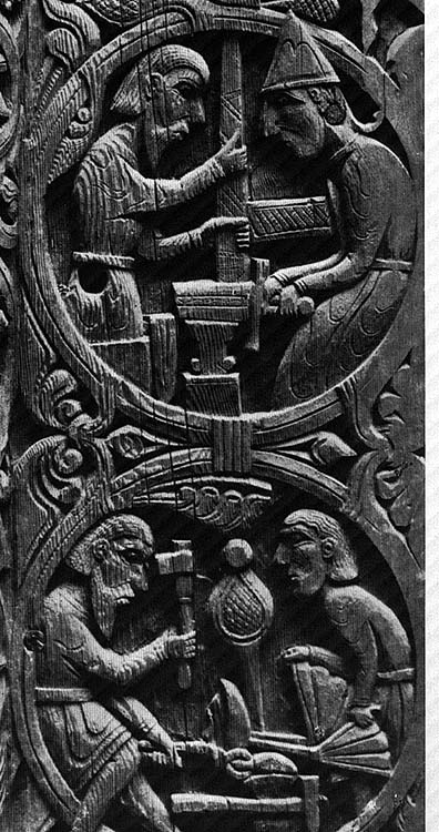
Is the main historic reference for any kind of bellows from the Viking Age. It is dated closer to 1150 and from the Hyllestad Church in Norway. There is a second carving - a top down view on a rune stone from Ramsund Sweden - but is more cartoon like and not directly associated with a human figure (no way to get measurements).
I have made a fair effort in trying to track down any actual physical remains of a bellows from the Viking Age (or anything before about 1200.) So far I have not found reference to a SINGLE artifact. What we have is only the two carved images above. Every time I hear about a bellows, it turns out to be a late medieval (or later) unit found inside a site with a much longer occupation history.
** If ANYONE has any hard evidence of an artifact bellows from the Viking Age - PLEASE send me an image or a publication reference!! **
What we do know is that larger and more prosperous farm steads from the VA often have special built small workshops with evidence of a forge within them. There is of course no way to prove if a bellows and anvil were owned by the farm - or supplied by traveling blacksmiths on a seasonal visit.
Thursday, January 03, 2008
Ritual and Meteors
At the risk of offending people's personal beliefs, I wanted to post this commentary on a web site recently sent to me to take a look at. The page (not given here to protect its author) Includes several commentaries on Ritual and Viking Age Blacksmithing.
The main source material - G.A.Wainwright's 'The Coming of Iron' - is listed as from the journal Antiquity, but the early date (1936) should be setting off some alarm bells.
Right off the top, the main thrust of the material is about Egyptian associations with iron - and should be questioned. This culture is technologically at the boundary between copper and bronze, not a primary iron age culture at all. Although there are a very few iron objects surviving from the culture, these are all meteoric iron. There is no evidence that the Egyptians themselves had any understanding of smelting iron. The oldest smelted iron objects come from northern Turkey and about 2000 BC (+/-).
The connection between streaks in the night sky and lumps of rock was actually not made until the 1800's. An argument could be made that the ancients knew things we did not - but this assertion can not be made based on negative evidence. In a practical sense, a farmer pulling up a large lump of strange metal in his field may have considered a supernatural origin. In a world where no iron existed. The leap from a rusted rock to streaks in the sky is a huge one.
I would be interested in reading the Wainwright article, but I suspect he is a linguist (?). Very much has been made - by Anthropologists - of determining ritual, but even the language they use is far removed from the practical world of the forge. (Take a look at all the stuff recorded on African iron smelting from the 1970's. Those guys may have painfully recorded every bit of clothing and working song, but they missed any understanding of the actual working method of making good iron!)
In a Scandinavian context, there is very little hard evidence about what (if any) ritual practices may be undertaken by the Norse. I have seen much attributed via Wicca and especially Astru - but frankly those are both VICTORIAN re-creations. My own general feeling (and please note that this is not backed by hard evidence) is that any Norseman would be trying to stay as far away from the powers of the Gods as possible. At best I would suggest a blurred line between practical ritual and effective technology. Much use of 'small R' ritual - and hardly any use of Ritual. A smith drinks a cup of mead (to steady himself - as you noted) and also spills a bit into the slack tub. This becomes just 'the practical thing you always do' - rather than a pre-meditated attempt to harness the powers. We moderns tend to think in terms of formal Religion - and in most cases I suggest the ancients did just the opposite. It might be possible to delve into the Sagas, but all that would be found would be mere scraps. The smiths themselves were unlikely to communicate their methods, and the tales are highly Christianized and recorded centuries after the events.
On the web site there is some speculation the possible special qualities of meteoric iron, but these miss the nickel content of the alloy. Metoric iron is distinguished by having a nickel content usually plus 5 - 7 %, sometimes as high as 15%. This alloy was not made 'artificially' in the smelter until the late Victorian period (latter 1800's). The difference is so specific and striking that this is how meteoric source is determined for artifacts. If you have ever tried forging modern stainless, the difference would be obvious to you - the stuff is darn hard even at bright forging temperatures. In an ancient world where every iron object rusted - something of meteoric iron would basicly not tarnish. Note that meteoric iron has no CARBON in it, so all those problems of carbon enrichment by the smith still remain.
When Scott Langton made his replica of the Sutton Hoo sword (back in the late 1970's - its the one on display in the British Museum), he included an alloy called L6 in the mix. L6 is a middle carbon, nickel content alloy (typically about .5 % carbon with something like .5 - 1% nickel). A good source for this stuff is old wood cutting band saw blades (not the bi metal ones). In your pattern weld, it will give you bright silver lines against the matte black of the high carbon and ropey texture created by wrought iron. (I use this mix too, so you would see it on my own web site images of past blade work - check 'Sword of Heroes')
Subscribe to:
Posts (Atom)


