This project was actually completed about two weeks back. I got involved in documenting the Icelandic Iron smelt (and a long workshop series here at Wareham).
As a review of earlier posts :
I did try to make some photo documentation of the ongoing process of actually making the replicas. (I do admit that I got a bit rushed into the final stages of making the key, shackle and the related hasp assembly, which are only shown as the final results.)
As I had mentioned in earlier descriptions, the chosen prototype was the decorated lock found at Coppergate in York (# 3610)
 |
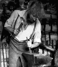
| The material for the locks was forged out from mild steel - 1/4 x 2 inch stock to the desired 3/16 x 2 1/2 size, using a replica of one of the Mastermyr hammers. You can see the progression from rough peening to spread through final smoothing (left side). This created a subtle surface effect that duplicates the original process of forging the starting strips from a currency bar. |
 |
| Portions of the longer bar were cut, then forged to rough cylinders over the edge of the anvil. These would form the body of each lock. This results in a slightly distorted shape - obviously different than simply using commercial pipe. |
 |
| A total of three bodies were made - you can see the variation between each. |
 |
| The seams of the cylinders were bronze braised. I had a wee bit of trouble getting a good finish at this stage. (You note that the third body was braised from the inside - far left. In retrospect, they should have all been done this way.) I did file / grind off the excess bronze at this point! I did use a modern torch for the braising heat. |
 |
| Forging the smaller cylinder that holds the top shackle loop. I forged a rough cylinder on the end of the bar, then used a (admittedly modern) hacksaw to cut off the cylinder. This was then forged tighter around a piece of 3/8 round bar as a central mandrel. |
 |
| One of the completed smaller cylinders. Due to the size / relative strength, these were not braised closed. |
The next step was braising each of the small shackle cylinders to the larger lock bodies. (Sorry - no images there.)
 |
| Next the two end plates were made. A triangular piece was cut from the remaining wide strip, two for each lock. (The pieces here are for the 'front' of each lock.) |
|
The individual forming steps on the end plates are shown above :
1) Grind to shape individually to fit each lock body
2) Hot punch the upper shackle hole (front plates only)
3) Drill small holes at the corners of the shackle (front) and key (rear) slots
4) Using different straight chisels, cut out the required slots
5) Finish by filing the slot edges smooth
Another 'modern cheat' here was using a modern drill press for the corner holes - rather than hot punching these.
A large segment of the work is not documented via photographs:
• A flat plate was prepared with two holes at one end. This plate was then secured inside the lock body. Originally these would have been bronze braised into place, I used a modern (invisible) cheat and MIG welded to secure.
• The keys were forged, fitted separately to each lock individually. One
end was split, then forged out to make an L shaped fork of two tines,
each formed to a circular profile that would then fit into the paired
holes inside the lock body.(And tested before the next step!) The other end of each was hot punched and drifted to make a carry loop.
• 3/16 square rod was twisted, then cut to make the short bars that secured the two end plates to the lock bodies. There were four such rods required on each lock. These were then used like long shafted rivets.
• Individual shackles were made from 3/16 x 1 inch flat stock, forged to roughly 5/16 inch round on one end (to fit into the small top cylinder and punched hole in the end plate). Each shackle was then formed to a U shape - again to fit the individual lock.
• Pieces of flat spring were prepared, two pieces for each lock shackle. Another modern cheat - I used some band saw blade material for these (suitable width and 'spring'). The pieces of spring were braised in place to one end of each shackle.
• The final step was determining the exact fit of the shackle slot - relative to the individual springs. There was a fussy balance between having the slot wide enough to make the key properly depress the shackle springs - and not having it too loose so the lock would not remain secure.
The overall project was then completed by forging the pair of strap hinges for each box. There was also a hasp set made for each box, using the same 'loop and tab' method used on various known Norse sea chests.
 |
| One finished lock, showing the shackle removed and the individually fitted key. Also the pieces of the hasp set (wrought head square nails were included for mounting). |
 |
| The completed pair of locks and hasps, showing one securing a hasp set. |
Opening one of these Norse locks is a bit of a handful (literally). You have to insert the key into the lock body, and pretty much feel / fit for the holes the fork ends fit through. Then you have to press hard enough to raise the two spring ends clear of the edge of the shackle slot. At that point you have to pull with both hands (maintaining the spring release pressure) to slide the shackle free of the lock body. Basically you have to haul against the hasp / chest weight, to pull the shackle clear.
The individual keys and shackles, although similar, are NOT interchangeable! (I did end up marking one of the sets so to distinguish which parts should work correctly together!)






 Posts


