Correcting Reported Air Volumes
One of the critical elements in any bloomery iron smelt is the amount of air provided to the furnace. Air, or more specifically the oxygen component, supports the burning of charcoal, so the production of both heat and reactive gases. In simplest terms:
O2 (air) + C (charcoal) = CO (heat)
CO + Fe2O3 (ore) = CO2 and Fe (bloom)
The mechanics of the air blast itself is a lot more complicated than just the chemical equation. Air volume effects the size of the burning zone, delivered pressure how far the burn zone penetrates into the furnace, and entry angle of the blast determines how the burning zone is positioned within the diameter of the furnace. ( see ‘About the Air’, blog post May 23, 2013 )
Most working teams actually don’t concern themselves with recording air volumes, as a much more practical measurement is how air blast effects charcoal burn rates. Over the course of a working smelt, knowing just how long it takes to consume a fixed measure of charcoal is one of the best indications of what is happening inside the furnace. Over past experiments, recording the addition times of fixed measures of charcoal has been a standard method of indicating shifting burn rates within each experiment. This instead of mathematically generating an average (total time against total charcoal consumed), a method commonly used by other teams.
Directly related to this, most other teams have one standard air production method, either repeated use of the same electric blower or human powered bellows. With any bellows equipment, obviously the greatest variation in delivered volume and pressure, minute by minute over the course of the long smelt effort, will
be through the differing activities of individual (changing!) bellows operators.
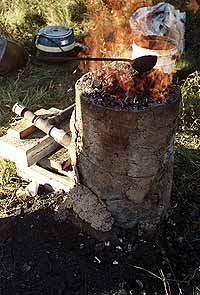
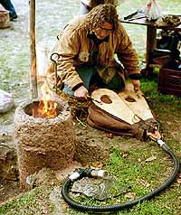
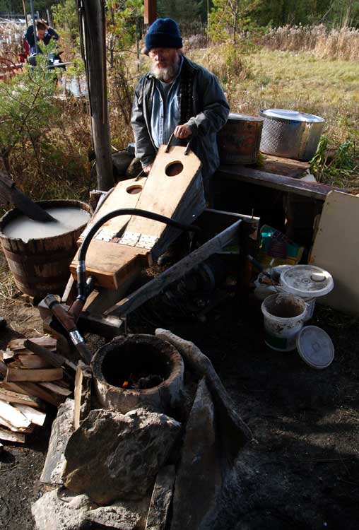
The long series of experimental smelts recorded here have seen a large number of quite different air equipment used, even when considering those used on multiple tests :
Vacuum cleaner blowers - two different
Norse blacksmith bellows - two different
Norse ‘smelting’ bellows - three different
‘Compression’ blower - the commonly used standard (seen below)
 |  |  |
Partially because of this wide variation in air equipment, there was an attempt made fairly early in our working series to at least roughly measure air volumes produced.
 |
| Current wind speed gauge, about life sized |
It has been mentioned numerous times, those working without Institutional support often can only provide the simplest of measuring instruments. I had investigated possible methods of measuring air volumes back in 2007, and what proved feasible was the purchase of a simple wind speed anemometer, a type used by sailors and wind surfers. The precision of this unit was low, and in retrospect, the durability of construction is likely to have further effected even that level of accuracy over time. With the gauge set in line, measurements would be recorded as a rough estimated average while observing for several seconds, as Kilometers per Hour. The KpH number combined with the pass through area (2.5 cm diameter) and a calculation made to convert to Litres per Minute. This was never considered more that accurate to within 25 LpM at best. Additionally, from the vary start it was recognized that any measurements from these methods could only be considered roughly approximate.
 |
| High capacity electric blower - US Navy surplus |
Set up of wind speed and pressure gauges, April 2008 (smelt 32 - D14).
Along with a 'box' fitting to hold the wind gauge, an additional fitting can be added to allow inclusion of a simple pressure gauge. This set up was used infrequently between separate smelts, plus only recorded irregularly during an individual experiment.
Air volume from the most commonly used industrial blower was controlled using a sliding plate styled ‘blast gate’. This had been marked with a set of lines roughly calibrated to 100 LpM amounts, determined as indicated above. Out of concern of the wear being caused by the high output speed of this blower, most frequently these marks would be used to record air volumes, not repeated use of the wind speed gauge (which was only left installed for the measurements).
Given the duplication of method, it should be considered that the air volume numbers recorded over those smelts using these systems should at best be considered ‘relative’, as a high level of variation in precision was certainly to be expected. One major reason for continuing with these methods, despite the known lack of accuracy, was to be able to make some estimation of the functional air delivery from the various human powered bellows equipments used. It was quickly observed that any theoretical volumes as calculated via dimensional measurements, were quite different than the actual working volumes produced. There was also considerable variations between individual operators, and even the same operator over even a short working cycle. (Further information on this can be found as ‘Air Delivery Test’ - October 2007 )

Neil Peterson had acquired a new, and significantly more accurate, air volume meter - the HHF1000 by Omega, which was available for the smelt on September 4, 2021. This instrument uses a small sensor that is positioned through a 6 mm diameter hole into a pipe section, with both direct digital read out and even the ability to wirelessly transmit data to a near-by computer. It makes readings down to every 1/4 second, with an expected accuracy of 1.5 %. Needless to say the addition of this significantly higher quality instrument can be expected to seriously improve accuracy of measurements into the future.
Over this experiment, four separate measurements were made using the new instrument. This was done roughly each time air flow was changed, that done using the simple marks on the sliding plate of the blast gate. Changes were made because of variations in burn rate or other observations of how the furnace was performing. The meter measurements were taken inside a 40 mm pipe section, the rough multiplier from meter reading to LpM is X 75. Note how there are clear gaps in the recorded measurements :
| Time | Event | Plate | Meter | Calculated |
| 10:11 | fill rough charcoal | 700 | ||
| 10:15 | air increase | (900) | ||
| 11:19 | full graded charcoal | 11.5 | 865 | |
| 11:23 | air reduced | 700 | (no record) | 550 |
| 12:00 | air increased | 800 | 8.8 | 660 |
| 12:44 | air increased | 900 | 9.6 | 720 |
What is significant to remember is that the plate marks are ‘hole size’ only (so a maximum amount available). There can be considerable changes in flow into the furnace as conditions inside change (charcoal size, any ‘draw’ effect as stack ignites, formation and position of slag bowl, amount of ore contained in the upper stack - all come to mind at the least). The meter is measuring the actual air flow at the time point indicated, so differences at similar plate marks should be expected. This is clearly seen even with this limited set, in the differences between the two measurements with the plate setting at 900 LpM, early with the furnace full of rough ‘out of the bag’ sized pieces compared to later in the smelt, with smaller gaps between graded charcoal, plus the addition of about 3 kg + of combined ore / slag pieces within the stack.
Clearly this limited set of measurements is at best a ‘proof of concept’, definitely not enough data to draw conclusions of the operating changes within the air / furnace system over the duration of a complete smelt!
Comparing the plate marks back to the volumes calculated from the meter readings shows an error factor of roughly plus times 1.25 (how much larger the plate mark is than the meter calculation). Although there will be some shifting of potential accuracy between the earliest wind speed gauge readings and the more recent (due to wear in the vane shaft), certainly this set suggests all the earlier numbers will be 20 - 25% higher than what was actually being involved at those times.
Obviously, an important set of observations can be gathered by leaving the new instrument in place over an entire smelt series (or at least taking measurements over a short set of time points overall). Although the pressure gauge now on hand is both an analog and far less precision unit, recording variations in delivery pressure will also provide some insights.
One important set of measurements employing this new gauge will be to undertake at least some of the air delivery from the next smelt using the current V3 Norse styled smelting bellows. At best, the current estimates for air delivery using this air system are based on measurements made using the earlier wind speed gauge as described above.









 Posts
Posts