Monday, September 20, 2021

Replacements and Improvements - Smelter Air systems

The September iron smelt proved problematic on several levels.


 The first contributing problem was the set up of the furnace, with the tuyere point set right above the extraction arch. This arrangement was dictated by the physical layout of the Hals sod cone build. Our normal build is to place the tuyere point at 90 degrees to the extraction arch. This places the air system well out of the way of the working area during extraction.

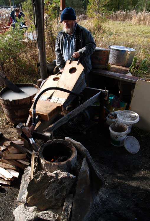
Air System in place at smelt start.

To provide clearance for the expected slag control steps, the pipe fittings used to conduct air to the tuyere were hung via chain off a metal bar, supported by a pair of uprights placed well to the sides of the gap in the sod structure. In addition to this long used element, a new section of plastic pipe had been added. This was for the introduction of a new air volume meter acquired by team second Neil Peterson.


The second thing was the level of damage after the first smelt in June. With a bottom extraction, especially given the thinner than our standard walls (at 4.5 cm), certainly a certain amount of breakage was expected. 

The bloom created was also much larger than expected, at almost 9 kg. As the mass was fairly spongy, that weight does include more slag than has been typical, but this actually increased the raw size of the mass that was pulled clear.

Then the 8 inch snapping turtle crawled in overnight, and broke away about a third of the front wall surface. 

The culprit, red line shows were piece seen to right was broken away
 

The Icelandic clay mix was expected to suffer more heat effects than our standard use of high fire EPK clay, and this certainly proved the case. There had been considerable erosion around the normal hot spot around the tuyere point. The original wall thickness reduced to as little as 1 cm at the location directly above the tuyere. (This can been seen in the lower wall section broken free by the turtle, laying to the bottom right in the image above.)

Furnace before start of repairs in August

In preparation for the Phase 3-B smelt, The lower section of the front of the furnace had to be significantly re-built. The extraction arch was framed up using the same side blocks and lintel piece as before. The area above this was built up of new clay mix. Another layer of clay was plastered over the eroded areas on the inside. 

The end result of all this was that there was a failure along the line between the fresh clay and the original wall surface (not entirely unexpected). Although certainly this did not prevent the full smelting cycle to proceed effectively, it did mean there was a major weakness along the edges seen above. 


The third thing was worker experience. It was decided (number of contributing factors) to let Rey Cogswell undertake the extraction. Although Rey had certainly observed the process several times, and assisted directly in the process at the June smelt, this would be Rey's first full attempt at an extraction. Understandably, Rey was tentative when working against the extreme temperatures and still uncertain about exactly how to manipulate the slag bowl to break the bloom free. Taken altogether, the work was not undertaken quickly enough, and the entire slag bowl and bloom complex had started to cool down. To be fair, the bloom was again high yield and spongy, meaning another excessively large mass.

Damage to the front of the furnace, right after extraction

This combination would result in breaking away the entire front bottom half of the furnace, pulling the tuyere and air system totally free, but still hanging from the supporting bar. There would also be a large fan of hot slag, furnace wall fragments and still burning charcoal pulled out of the furnace and into the slot in the sod structure. In the (normal!) haste to get the bloom mass over to the stump for the initial compaction hammering, this left the air system connections exposed to the concentrated heat from this debris.


Which is a long explanation of why it proved necessary to replace a number individual pieces of the long standing air system.

The fittings have long been 1 1/4 inch ID threaded pipe. This has allowed for simple modifications to the basic T format, with various different fittings available for the downstream end, to mate with the different tuyeres that have been used. Opposite this is a fitting that can quickly be unscrewed to allow for probing down the inside of the tuerye to clear any blocking slag. The original view port was a simple plexi disk, sealed on to the end of this fitting. (One of the casualties was this plexi, admittedly getting pretty scratched up from 15 + years of use.)


Tuyere to Port at bottom, air flow / pressure at left, pipe connects at right

Larger viewing glass towards air pipe diameter.

I had picked up a number of thick glass disks (from projector units) a number of years ago, each a bit over 2 1/2 inches in diameter. With a lot of picking and matching, I was able to get component pieces of plumbing fittings at my local hardware that let me mate up the glass disk to the air supply T. The result does include one rubber section and one plastic. In use to clear blockages with the customary 3/8 diameter rod, the whole end unit would screw free from the short double threaded section seen directly attached to the T connector above.

I also made up replacements for mounting either the straight section required for the probe of the new air flow gauge, or to include the nipple for the (older) air pressure meter. Either these, or the short double threaded pipe would be at right angles to to the tuyere / port combination. I was recently able to get a roughly 6 foot section of flexible solid metal piping (normally used to duct auto exhaust at repair shops) - Thanks to my old friend Lloyd Johnston. This pipe is about 3 inches ID, so the additional element allows a flexible coupling to a plastic piece that will fit nicely down the interior of that metal pipe. (One serious advantage, beyond durability, is that this metal pipe has a relatively smooth interior, and does not create the loud whistling noise from the corrugated plastic tubes in use up to recently!)

Blower side elements : sliding blast gate / Y to attach a second air supply.

 One of the major experimental elements to undertake is getting much more accurate data on both air volumes and pressures, not only for our standard high capacity electric blower, but also for the various human powered bellows used in the past. As detailed in an earlier posting : Mind the Blast the measurements recorded up to now should be at best considered approximate. The new flow gauge is capable of both measuring, and recording (via computer) extremely detailed data, over the progress of an entire smelt, minute by minute.

It would be quite valuable to our understanding of the dynamics with various human powered systems to also be able to generate comparison numbers. The main problem with this is not in instrumentation, but in the raw labour required to work an entire smelt (four to six hours!) using bellows. To that problem, I made up an additional element, which can be screwed in place downstream of the normal sliding plate air control. This has a one way (sump pump back flow) valve. Although not tested yet, the hope is that with this element in place, the bellows can be utilized for short periods, by using the blast gate to seal output from the electric blower. The one way valve should effectively seal air from the blower escaping through the bellows side when the blower is powering the air supply. 


My hope is to undertake at least one of these bellows comparison and recording tests for the next upcoming smelt...

Saturday, September 18, 2021

Sod vs Turf?

I've never been to Iceland.

(Although at least my primary smelting partner, Neil Peterson, has.)

One of the important materials for the Viking Age iron furnaces at Hals, Iceland, is the use of cut ground cover - 'turf' for the structure of the furnace.


Of course after 1000 years and with only an field report to base measurements on, exact details are hard to determine. The original report had the excavation diagrams as quite small scale, and only in grey scale. The text describes the turf blocks seen in the cross section cut along the edge of furnace shaft III as being about 10 cm thick. (1) Recently Kevin Smith had provided us with larger sized versions, also in colour and with a more complete key to the elements represented (2). The version seen above has been modified and printed to graph paper (seen lightly in the scan) at one square at roughly 10 cm. The lower diagram is my own interpretation of how that furnace would have been originally constructed. More or less taking the line of the shaft, and pushing it back to vertical, shifting the individual turf strips against this line. (This would be the guide for the construction of the furnace used for the June 20 and September 4 tests.)
 
One of the certain problems with attempting to design any experimental archaeology project is always 'how close can you get'. Our long standing work related to Hals (since 2007 / now 10 smelts) has included many elements which may be at best approximations :
- use of DD1 (Fe2O3 / red oxide) ore analog : not natural bog (FeO-OH) ore
- (most recently) simulated clay mix : not local Icelandic clay
- stones of Ontario granite or gniess : not Icelandic basalt
- sand of Ontario granite origin : not from Icelandic basalt
- charcoal of either white oak or hard maple ; not Icelandic birch 
- local Wareham cut grass sod : not natural Icelandic turf

In recent discussions, the question of terminology over this last aspect arose. It is obvious that that environmental conditions around West Central Iceland at Hals would be significantly different than those at Wareham, in Central Ontario. Growth cycles are not comparable, as well as the types of natural vegetation. This is compounded by the fact that the yard at Wareham was started as an artificially laid course of commercial grass sod, laid over a new graded surface about 35 years ago. This has been left largely untended, so whatever natural plants growing locally have slowly encroached. One specific change has been the dominance of 'twitch grass' in many areas, which chokes out other plants (itself an invasive species). 
 
June furnace, before start of August repair.

 
The overall result is that any cut blocks of the upper grass layer are more dirt than root mass. This is important related back to use of this local grass sod for furnace construction. The roots are what holds the dirt in place, securing the structure.  When this organic material is exposed to the heat of a working furnace, the roots simply burn away. The now hot dirt quickly looses any structure, and will fall apart and flow almost like water. Eventually, and especially if exposed to full temperature furnace gasses (at the range of 1150 - 1250 C), the silica components of the dirt can fuse into a fragile mass.  
In the image above, taken the day after the first full smelt of that furnace, you can clearly see the failure of the inner edges of the stacked grass sods, where heat had penetrated through the relatively thin (4.5 cm) inner clay liner.

I wondered how I might detail what I see as a major difference between the Ontario (semi wild) grass sods cut here at Wareham, to the Icelandic turf used at Hals. 

I still had a couple of pieces of the sod I had cut for use in the June build left over. 
From this I cut a block, as close as I could manage, at 20 x 20 cm, trimmed to 10 cm thick. The precise measurements are 20 x 19 cm, thickness tapers slightly from 11 to 10 cm. I used hand shears to trim the grass fairly close to the ground surface. 
 
Cut block : 3/4 view
 
View of the front edge


The weight of this block, as damp and 'living' is roughly 5 kg (5093 gms including the metal tray it is sitting on)

The intent here is to leave this block exposed to the sun for a length of time to start to remove the contained water. 

- Next the piece will be heated (likely by placing the tray on the top surface of my wood stove) to remove any final moisture. 

- At this point the material will be weighed again (so giving some idea of the water weight).

- When the block is 'bone dry', it should be possible to knock off the dirt from the root mass. This will allow for photographing the root web, and most importantly weighing just the contained dirt for comparison back to the starting amount. 

This all should allow for some kind of comparison 'root to dirt' measurement. 

This exercise is more likely to be only of qualitative (rather than precise quantitative) value. The hope is that this test might proved some data towards what up to now has been a gap in my personal experience with Icelandic conditions. 


1) Smith, K.P., 2005, "Ore, Fire, Hammer, Sickle: Iron Production in Viking Age and Early Medieval Iceland", AVISTA Studies in the History of Medieval Technology, Science, and Art, Volume 4, USA

Also available as PDF on line : https://www.academia.edu/191535/Ore_Fire_Hammer_Sickle_Iron_Production_in_Viking_Age_and_Early_Medieval_Iceland

2) A overview of both the Hals site and these experiments is currently under preparation, co authored by Smith, Markewitz and Peterson (‘Now with 70% Less Clay! Experiments with Viking Age Icelandic Turf walled Iron Smelting Furnaces’) A short video overview was presented at the recent EAC 12 virtual conference, available on line : https://youtu.be/7Ltz5NG2BP0


Wednesday, September 08, 2021

Mind the BLAST

Correcting Reported Air Volumes


    One of the critical elements in any bloomery iron smelt is the amount of air provided to the furnace. Air, or more specifically the oxygen component, supports the burning of charcoal, so the production of both heat and reactive gases. In simplest terms:

O2 (air) + C (charcoal) = CO (heat) 

CO + Fe2O3 (ore) = CO2 and Fe (bloom)

    The mechanics of the air blast itself is a lot more complicated than just the chemical equation. Air volume effects the size of the burning zone, delivered pressure how far the burn zone penetrates into the furnace, and entry angle of the blast determines how the burning zone is positioned within the diameter of the furnace. ( see ‘About the Air’, blog post May 23, 2013 )


    Most working teams actually don’t concern themselves with recording air volumes, as a much more practical measurement is how air blast effects charcoal burn rates. Over the course of a working smelt, knowing just how long it takes to consume a fixed measure of charcoal is one of the best indications of what is happening inside the furnace. Over past experiments, recording the addition times of fixed measures of charcoal has been a standard method of indicating shifting burn rates within each experiment. This instead of mathematically generating an average (total time against total charcoal consumed), a method commonly used by other teams.
    Directly related to this, most other teams have one standard air production method, either repeated use of the same electric blower or human powered bellows. With any bellows equipment, obviously the greatest variation in delivered volume and pressure, minute by minute over the course of the long smelt effort, will
be through the differing activities of individual (changing!) bellows operators.

The long series of experimental smelts recorded here have seen a large number of quite different air equipment used, even when considering those used on multiple tests :

Vacuum cleaner blowers - two different
Norse blacksmith bellows - two different
Norse ‘smelting’ bellows - three different
‘Compression’ blower - the commonly used standard (seen below)


Partially because of this wide variation in air equipment, there was an attempt made fairly early in our working series to at least roughly measure air volumes produced.

Current wind speed gauge, about life sized
 

    It has been mentioned numerous times, those working without Institutional support often can only provide the simplest of measuring instruments. I had investigated possible methods of measuring air volumes back in 2007, and what proved feasible was the purchase of a simple wind speed anemometer, a type used by sailors and wind surfers. The precision of this unit was low, and in retrospect, the durability of construction is likely to have further effected even that level of accuracy over time. With the gauge set in line, measurements would be recorded as a rough estimated average while observing for several seconds, as Kilometers per Hour. The  KpH number combined with the pass through area (2.5 cm diameter) and a calculation made to convert to Litres per Minute. This was never considered more that accurate to within 25 LpM at best. Additionally, from the vary start it was recognized that any measurements from these methods could only be considered roughly approximate.

High capacity electric blower - US Navy surplus

Set up of wind speed and pressure gauges, April 2008 (smelt 32 - D14). 

    Along with a 'box' fitting to hold the wind gauge, an additional fitting can be added to allow inclusion of a simple pressure gauge. This set up was used infrequently between separate smelts, plus only recorded irregularly during an individual experiment.
    Air volume from the most commonly used industrial blower was controlled using a sliding plate styled ‘blast gate’. This had been marked with a set of lines roughly calibrated to 100 LpM amounts, determined as indicated above. Out of concern of the wear being caused by the high output speed of this blower, most frequently these marks would be used to record air volumes, not repeated use of the wind speed gauge (which was only left installed for the measurements).

    Given the duplication of method, it should be considered that the air volume numbers recorded over those smelts using these systems should at best be considered ‘relative’, as a high level of variation in precision was certainly to be expected. One major reason for continuing with these methods, despite the known lack of accuracy, was to be able to make some estimation of the functional air delivery from the various human powered bellows equipments used. It was quickly observed that any theoretical volumes as calculated via dimensional measurements, were quite different than the actual working volumes produced. There was also considerable variations between individual operators, and even the same operator over even a short working cycle. (Further information on this can be found as ‘Air Delivery Test’ - October 2007 )


    Neil Peterson had acquired a new, and significantly more accurate, air volume meter - the HHF1000 by Omega, which was available for the smelt on September 4, 2021. This instrument uses a small sensor that is positioned through a 6 mm diameter hole into a pipe section, with both direct digital read out and even the ability to wirelessly transmit data to a near-by computer. It makes readings down to every 1/4 second, with an expected accuracy of 1.5 %. Needless to say the addition of this significantly higher quality instrument can be expected to seriously improve accuracy of measurements into the future.

Over this experiment, four separate measurements were made using the new instrument. This was done roughly each time air flow was changed, that done using the simple marks on the sliding plate of the blast gate. Changes were made because of variations in burn rate or other observations of how the furnace was performing. The meter measurements were taken inside a 40 mm pipe section, the rough multiplier from meter reading to LpM is X 75. Note how there are clear gaps in the recorded measurements :

TimeEventPlateMeterCalculated
10:11   fill rough charcoal     
700    

10:15air increase
(900)

11:19full graded charcoal

11.5    865
11:23air reduced
700(no record)    
550
12:00air increased
8008.8660
12:44air increased
9009.6720

    What is significant to remember is that the plate marks are ‘hole size’ only (so a maximum amount available). There can be considerable changes in flow into the furnace as conditions inside change (charcoal size, any ‘draw’ effect as stack ignites, formation and position of slag bowl, amount of ore contained in the upper stack - all come to mind at the least). The meter is measuring the actual air flow at the time point indicated, so differences at similar plate marks should be expected. This is clearly seen even with this limited set, in the differences between the two measurements with the plate setting at 900 LpM, early with the furnace full of rough ‘out of the bag’ sized pieces compared to later in the smelt, with smaller gaps between graded charcoal, plus the addition of about 3 kg + of combined ore / slag pieces within the stack.
    Clearly this limited set of measurements is at best a ‘proof of concept’, definitely not enough data to draw conclusions of the operating changes within the air / furnace system over the duration of a complete smelt!

    Comparing the plate marks back to the volumes calculated from the meter readings shows an error factor of roughly plus times 1.25 (how much larger the plate mark is than the meter calculation). Although there will be some shifting of potential accuracy between the earliest wind speed gauge readings and the more recent (due to wear in the vane shaft), certainly this set suggests all the earlier numbers will be 20 - 25% higher than what was actually being involved at those times.


    Obviously, an important set of observations can be gathered by leaving the new instrument in place over an entire smelt series (or at least taking measurements over a short set of time points overall). Although the pressure gauge now on hand is both an analog and far less precision unit, recording variations in delivery pressure will also provide some insights.
    One important set of measurements employing this new gauge will be to undertake at least some of the air delivery from the next smelt using the current V3 Norse styled smelting bellows. At best, the current estimates for air delivery using this air system are based on measurements made using the earlier wind speed gauge as described above.


Thursday, September 02, 2021

30 That Never Sold - 'Wind Widgets'

 The last couple of years I exhibited at Summerfolk in Owen Sound, I mounted a series of work based on the Four Elements : Earth / Air / Fire / (Water).

I never completed the last element, work based on water. This largely because of repeated trips to Scotland and Europe after 2014, to participate in bloomery iron research projects, all over that same part of later August. 


For the 2013 year, the theme at Summerfolk was AIR.

In an attempt to have a body of lower priced objects, that I thought suitable and of interest to a Folk Festival audience, I had created several styles of individually made 'Wind Widget' outdoor spinners. These were all made of durable metal, unlike the slightly cheaper plastic spinners becoming available about the same time. There were two broad groupings, either made of solid copper or brass, plus those made of aluminum or stainless steel. Some of the curved aluminum ones were spray painted  with merging bright colours.

The more expensive (considerably!) material copper and brass were priced $20 (taxes included). The aluminum and stainless were priced at $16 (taxes in)

I don't think I sold one...


I still have over 30 of these. I personally think they are good objects. The spirals and mobius strip types are roughly 8 - 10 inches in diameter, the strip versions about 18 inches long. With the light weight against the curving surfaces, they all are quite mobile to the wind. They certainly are extremely durable - I've had some of the first prototypes for these hanging outside at Wareham, year round, for a decade.


And no - I've never been able to 'Understand the Marketplace'.


February 15 - May 15, 2012 : Supported by a Crafts Projects - Creation and Development Grant

COPYRIGHT NOTICE - All posted text and images @ Darrell Markewitz.
No duplication, in whole or in part, is permitted without the author's expressed written permission.
For a detailed copyright statement : go HERE