Saturday, May 31, 2008

Viking Ships at Roskilde

(Repeated from the DARC blog)
Today is smelter prep / workshop day for DARC, against our upcoming spring smelt on June 14. So I wanted to get my presentation version of my Denmark images sorted out and transfered over to DVD. At this point I have taken the various panoramic images I shot and patched them together. As a bit of a break from my concentration on iron smelting here, I have posted a couple of images from the Viking Ship Museum in Roskilde.
View of the interior - Note that the ship is tied to the dock on the STARBOARD side.View of the hull at the waterline on the port side
The first are two views of the 'Ottar', a reconstruction of Skuldelv 1. This is a knorr (knarr over here), an ocean going freight vessel. The original was built in Sognefjorden Norway. This is the hull that Paul Compton's 'Viking Saga' is based on.
The specifics from my notes:
length - 16.5 m
width - 4.5 m
capacity - 20 tons / 35 cubic meters
draft (laden) - 1.3 m
sail speed - 12.5 knotts (empty?)
construction - Denmark, circa 1030
View of the interior, this ship tied 'to port'.
The last I am pretty sure is the reconstruction of Skuldelv 6. This is a medium sized coastal working ship for fishing or trade. There were a number of boats at the museum dock on this basic pattern These are obviously the work horses of the sailing programs there.
The specifics (from the text):
length - 11.2 m
width - 2.5 m
capacity - 3 tons
construction - Norway, circa 1030

I got more detailed in my notes with the other museums I visited. I had wandered over the dock area before the museum opened in the morning to take these images. My main focus at the Viking Ship Museum was actually on construction and especially working tools. (This related to an ongoing project for Parks Canada to produce a complete set of Viking Age ship building tools.)

Wednesday, May 28, 2008

Norse Welding Flux?

As you may have seen, I started Hammered Out Bits mainly as a means to record and share the longer e-mail responses I was sending out almost one per day. Although the information contained below may be well known to many of the metalsmith readers, I figured I had the piece already written...

"... I am a 14 yr old student who is studying vikings. I am trying to find out what the vikings used in order to weld. I cannot find it in any of our libraries books. I know that the modern blacksmith can use borax. Did the vikings use this or something similar? "

Thats a pretty good question:

Borax is commonly used by * modern * and * north american * blacksmiths. Its what I use in my shop here. There are a couple of different versions available. You can purchase a product called 'Easy Weld', which is borax mixed with iron filings. The wee bits of iron dust make the two pieces you want to join tend to stick together quickly, but also leave the welded surfaces covered in lumps. So this stuff is ok for big structural work (or for a horse shoe) but not any good for finished work (say like pattern welding on a sword).
You can purchase chemically refined (water removed) forge borax. This stuff works great, but its pretty darn expensive (although you don't need very much). At something like $50 a kilo its more than I want to spend.
I use plain old washing borax from the grocery store - like '20 mule team'. This has the water still in the chemical, so it bubbles up a lot when applied to the red hot metal. But its also cheap, at something like $5 for a 2 kg box.

Now - borax is a chemical that only occurs around some specific dry lakes usually found in deserts, where the water evaporates and leaves the powered chemical behind. None of that in Northern Europe (that I know of?).

The tradition in England, and in Denmark (at least) is to use a fine while silica sand. I know smiths still working in both countries that still use sand as a flux when welding. I must tell you that I personally have not ever done this! What I have been told (and it fits the chemistry) is that the metal needs to be hotter before the sand flux is applied (higher melting point for silica) than would be used with borax. This suggests more skill for the smith.

The reason here is that the purpose of the flux in the first place is to seal the surface of the bare metal from the effects of oxygen. The iron oxide, a dark scale, that forms on the metal surface when heated and exposed to oxygen, will not weld. So you would want to carefully watch how much air you blew into the fire, then very quickly pull out and apply the sand flux to seal the surface.A classic forge welding image. The bright sparks are actually droplets of hot liquid slag being forced outwards under the hammer stroke.

Then when the metal pieces are heated further to the correct temperature (a bright yellow to white) they are quickly moved to the anvil and stuck with the hammer. The series of blows have to overlap, moving from the centre of the pieces towards the edges. This compresses the joint to squirt out the flux between the pieces. Hopefully the now liquid flux also lifts away and washes out any oxides or dirt that may be between the pieces (or you get a failed weld). The trick is to hit hard enough to squirt out the flux and compress the pieces to fuse them, but not so hard as to completely distort the very hot (thus very soft) metal. Oh - and do this all working darn fast - as the metal will cool from 'welding heat' in mere seconds.

Did I mention that your Norse anvil is maybe 10 x 10 cm and maybe 5 kg - or maybe even a rock? Different metals have different welding temperatures too. Makes you understand how difficult is was to produce a pattern welded sword in the Viking Age.

You might find some more information related to Norse and Saxon knives and their construction on the blog (below). I have an article on Viking Age knives I was working up also on line:

http://www.warehamforge.ca/norse-knives/

I would suggest flux for the Viking Age is most likely going to be white silica sand. I do note however that is is just the kind of thing that is pretty hard to state for certain. You would have to pour through chemical details on academic reports on the archaeology for any evidence at all - assuming any one has ever closely examined the question.

Welcome to the world of artifacts and archaeology!

Tuesday, May 27, 2008

DeMystifying Layered Steels

Josh wrote:
" Can you turn me on to some information regarding techniques I need to start forging layered blades. ... What {alloys} do you recommend and how many folds do I need to attain the proper bond before I forge the third steel to the others. I know 512 layers is the damascus requirement and need your advice on the specifics. Are you thinking about making a layered bladesmithing video? "

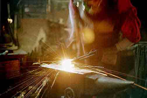
I started working on a new DVD - 'Basics of Layered Steels' back in winter of 2007. I own a VHC camcorder (and a half decent one). I shot about 2 hours of rough footage, some of it of objects now sold. It turned out the tracking is off on the camera and all the footage has a fold line through it and flips regularly. Not at all suitable for conversion to an educational program. And to top it off, no one will work on a 15 year old camcorder.
I have bought three digital cameras over the last year. All with problems - the last was a new Canon, but the power system completely crapped out mere days after the warranty period. Will cost as much to repair as to replace with a brand new one.

So the long and short is that I was working on a program on Layered Steels - but the whole thing is on hold pending equipment.

Josh's request shows some pretty typical misconceptions about layered steel. Much of what is written is incorrect or misleading. In one especially well known series of books on the topic, what is MISSING is more important than what is included. Too many smiths have taken the approach of framing their descriptions of their own work as mere advertising or even mysticism - merely to make for better sales!

As an initial starting point, take a look at my information on the Wareham web site (although elementary). I have also a number of past blog postings on various layered blades I've made over the last couple of years. (try searching under 'bladesmith' and 'knives')

Ok - this is the very quick (!) basics:

- the hard layer gives the cutting edge (durable but brittle)
- the soft layer gives the flexibility (soft but bends)
- the net result of adding soft to hard is to effectively REDUCE the edge holding - a straight mono blade of high carbon will always keep the best (hardest) edge, but at the risk of being too brittle.
- three layers of soft / hard / soft may prove the best balance of edge and durability (but its boring to look at)
- when welding, typically your outside surfaces should be plain mild steel. It takes more abuse, and is the cheapest material
- number of layers is only critical in terms of decorative effect. Low layers have few lines, generally less interesting visually
- remember that layer count goes up EXPONENTIALLY. A 2000 layer blade may only be one more weld from a 500 layer one
- remember that work effort should be counted by number of welds, not number of layers.
- extremely high (plus 1000) layers will suffer from 'carbon migration' effect (layers in effect blend together)
- I * personally * find the nicest patterns at about 250 to 500 layers (depending on method) - so 4 / 5 welds
- PATTERN WELDING (museum definition) is applied to twisted rod method (Northern European)
- variations in metal content react differently to acids, so are chosen for decorative effects
- etching can give two effects, shift in height (typically Nitric or Sulphuric) and shift in colour (typically Ferric Chloride)
-acid chosen may be determined by metal alloys in the mix

Personally, I tend to stick to the following construction:
-starting pile at between 9 - 13 layers (9 most typical) I usually have a long piece of mild steel in the centre as a handle
- I still like to wire the piles together for welding (just old fashioned I guess)
- two weld / draw sets - to about 50 layers
- at this point twist rods that will make up the back of the blade
- two layered blocks are welded to a piece of high carbon (for the cutting edge)
- Weld together edge and back pieces for the billet
- use L6 (.5% stainless about .5 % carbon) for decorative effect (produces thin silver lines)
- use wrought iron (antique) for decorative effect (produces 'rope' texture)
- etch first in Nitric, which changes heights of metal layers (topographic etch)
- etch second in Ferric, which brings out extremes of colour (surface effect only)

You can see a number of my past blades using layered steel HERE

The images are of my last blade commission (April 2008). This Viking Age man's knife is a typical seax type. Blade length is about 5 inches. The handle is a simple section of caribou antler.

The blade is pattern welded. In this case there are three separate twisted rods that make up the back. The edge is formed of two additional blocks welded to a high carbon core. The total layer count for the blade is 261.
I started with a pile of 13 plates. The mixture contains Mild steel / L6 / High carbon (1095 file) / wrought Iron:
M/L/H/L/M/I/M/I/M/L/H/L/M
With the central mild steel layer extending as a handle for the billet. You can see that 5 out of the 13 plates (actually about 50% of the material) is comprised of mild steel.
First weld - 13 layers (draw, cut to 4)
Second weld - 52 layers (draw)
At this point 2/3 of the bar was twisted in three sections, then cut
The remaining 1/3 was drawn, cut in half and matched to a carbon steel core
Third weld - edge at 105 layers
This was then forged to match the three twisted bars
Fourth weld - 261 layers
Forge to blade

As I have mentioned in other posts here, I have taken to making my knives using this method of a separate carbon steel core for the cutting edge with additional twisted rods forming the flexible and decorative back.

Sunday, May 25, 2008

'Espelund' Two Stage Process - Overview

(The following is converted from a posting to EARLY IRON)

Skip Williams wrote:

Espelund has had the idea for several years that his 'dust ore' was smelted in a two step process. It makes sense that the first step would be to sinter the ore in a furnace at an orange temperature and a low air rate until it sticks together. The second step would be to break up the sintered ore to 'normal' smelting sized particles and then smelt it in a bloomery furnace.

*********

Some maniac from Canada volunteered for a first test of that Espelund two stage process at the Heltborg event (in Denmark). And no, I have not crunched the numbers and formatted the images or written a report (yet).

As some of you know, Arne can be a bit difficult for us 'thick headed Poles' (sorry - in joke from the Seminar) to effectively communicate with. He is firmly entrenched in his viewpoint of analytical chemistry. Which of course explains much - but is often quite hard to convert to direct physical action. For the working iron maker, the answer to 'how much air' has to be answered in terms of at least litres per minute - not moles per smelt event. (In most cases, thats really more like 'pumps per minute' on an individual bellows. Arne often states that he finds our experimental process sloppy and lacking in critical measurements. He is most certainly correct - from the viewpoint of strict analytical science. Us working grunts however have such limited resources and are trapped by working in the dirty field, not a sterile laboratory.
Our efforts are ore to IRON - and the slag is just a waste product. Few of us even bother to weigh slag after the smelt, and there are extremely good practical reasons why NOT to bother. (more on that in a separate posting).

So - given what I could understand was the framework of the two step process, the sequence goes like this:
Step one is ore to iron rich slag mass
Step two is broken slag to bloom

If I got his point of evidence correct, he has examined a number (?) of Viking Age (?) iron smelting sites in Norway that show considerable volumes of materials (multiple smelts). At these locations he found remains of broken up slags, which looked like they were being intentionally prepared from larger slag blocks, and being collected for possible use as furnace charges.

I may have missed the point, but he did keep referring to 'broken slag' - not 'partially sintered ore'.

I saw two large potential problems with the process as he described it:
1) a duplication of effort and resources. Why run what was 'almost' a complete furnace operation (set up, cycle time, charcoal expended) just to produce a slag? Why not just run that operation (correctly) complete straight through to metal bloom?
2) breaking the slag mass from step one to prepare for step two is a HUGE amount of work. We all know how difficult it is to physically smash up slag compared to the effort required to prepare ore itself.

Anyway, without being able to provide (at this point) the exact details, the rough sequence of the experiment at Heltborg was like this:

The smelter used was a pretty standard 'short shaft' furnace:
Interior roughly 25 cm
working height about 30 - 35 cm above tuyere (55 total from base)
modified front plate (bellows tube tight to plate surface)
tuyere set about 10 cm above floor of smelter
provision for slag tapping, but not required

consumption rate of charcoal averaged about 10 minutes per kg (8 - 12 minute variable)
ore was added at roughly 2 kg per 1 kg of charcoal
total ore added was 14 kg
ore used was the 'Guldager' material (from Michael Nissen)

total production of slag was 11.2 kg
main slag mass was 7.5 kg
fragments recovered were 3.7 kg

The furnace was re-set, and Arne broke up the slag mass into typical sized pieces (roughly 'half walnut' or less) and sorted by eye.
The second firing:

working height about 50 cm above tuyere
tuyere angle at 22 down
(otherwise identical)

consumption rate of charcoal averaged about 7 minutes per kg (6 - 8 variable)
slag was added at roughly 1.5 kg per 1 kg of charcoal
total slag added was 7.75 kg

only a few small fragments of metal were recovered

So - right off the top, remember that this was the first working attempt at a brand new method. Two entirely new processes, plus some integration between these two - all three parts unknown.
On part A we got iron rich slag. How iron rich awaits tests by Arne of the samples he took.
On part B we did not achieve a viable iron bloom.

As Arne said ' Even a negative result is a valuable experiment '. I certainly would expect that to get this whole linked process working correctly, the development process will take as least as long as for two different smelt methods. (We all remember how long it took us to finally get any iron when we started!)

There are a number of what I feel are extreme challenges to get this process to work correctly. (This assuming that I got Arne's instructions on the chemistry correct.) What I recorded in my notes (please forgive me if I have this wrong!)

On the first step, the temperature range is extremely tight:
Require at least 1100 C to produce a working slag
But no more than 1200 C - which is "the threshold for CO production" (keep below to keep ore from reducing).
This is just way too tight a working range for the primitive equipment of an ancient smelter.

Anyway, that is the bare bones of the experiment. I'll let everyone know here when I get the experimental sequence formated and posted, plus the photographs of the process ready on the web site.

Darrell
 

February 15 - May 15, 2012 : Supported by a Crafts Projects - Creation and Development Grant

COPYRIGHT NOTICE - All posted text and images @ Darrell Markewitz.
No duplication, in whole or in part, is permitted without the author's expressed written permission.
For a detailed copyright statement : go HERE