
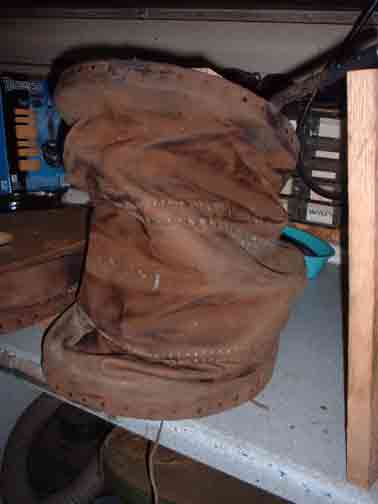
The image is loading directly from its internet source - the University of Pittsburgh.
http://www.pitt.edu/~dash/sigurddoor.html
http://www.pitt.edu/~dash/sigurdstone.html
Both by Professor D. L. Ashliman of the University of Pittsburgh
The core members of the DARC smelt team (Neil, Kevin, Dave and Ken) where up over the past weekend. We discussed what we are learning, what we have done, and what direction this year's campaign at the smelter should take.
The main thrust will be work towards the reconstruction of the Icelandic grass sod smelter. At present we have to pieces of technical work to refine. The first (not dealt with there) is the creation of a workable bog ore analog. The second is to finally get an effective bellows design.
Considerable background help on this has come from Jens Jørgen, who works at the living history side of the Heltborg Museum in NW Denmark.
Unfortunately the museum web site does not seem to detail the iron age farmstead reconstruction where Jens works as blacksmith and also smelts iron.
He has posted up a number of images related to the iron demonstrations and his bellows specifically.
There is one primary reason why the current bellows reconstruction (detailed over the last couple of postings here) does not work as expected when applied to an iron smelting furnace. The actual air volume produced is significantly less than the projected theoretical volume. (It should be noted that this bellows design and construction has proved very effective for blacksmith's forges and for bronze casting.)
Neil has pointed out that even small changes in the measurements can produce large variations in potential air. Using the new set of measurements from the bellows directly and he crunched the numbers. The highest possible *theoretical* volume produceable by my reconstruction is in the range of 500 - 600 LpM. So with the * actual * measured volumes at closer to 150 - 200 LpM - what the heck is going on?
So I did what I should have done at the start of this - I dragged the bellows out and set it up inside my (heated) studio. I pumped and measured and took photographs. I looked and pumped and measured some more. Then I thought about it and looked again.
When I had initially made the reconstruction blueprints, I had tried some body positions for the operator - just faking it. I based things like handle positions and most importantly - the amount of lift - based on that. This suggested to me that the maximum extension of the top plate could be 46 cm. I cut the fullness of the leather bags to allow for that elevation. There are three lens shaped pieces to the bag, each about 15 cm at the widest point.
In actual use however - what the operator * really * does is raise that plate to only 30 cm (less when the bellows is mounted at waist height on a forge table). The net effect is that one complete leather section is not being used. Since there is more bag that required, the whole bag collapses sideways and crumples - effectively reducing the amount of air inside. On the exhaust stroke - that extra leather has to be compressed - and so the plate can not be depressed as far as it might be with a loss of volume again.
My only excuse here is that I'm usually the one on the bellows - or have my head stuck inside the smelter - or trying to organize a 3 - 6 person team - or running back and forth to the workshop trying to find tools...
The operator of the bellows can't actually SEE this folding and distortion of the bag. Its only really obvious from just behind and at the same eye level as the bellows. As an uninvolved observer. We also gave up on use of the small bellows after I met Lee and Skip the first time and they told us about the correct use of higher air volumes.
On top of that, I think the leather I used may also be a bit heavier than required. (At the time I had access to a large amount at a good price.) There are wire stiffeners along the double seam lines - but these would be better replaced with metal rod hoops (like 1/4 round rod).
1) Neil has ordered a copy of the small blacksmith's bellows for his glass bead furnace project. This will be made up using the current physical measurements, but with two important changes.
- First the bag will be cut with only two leather lames - giving a maximum loft in use of 30 cm. This will reduce the folding of what is just unused leather surface. The wooden frame will be made up, and then a fast test bag will be made up out of taped plastic. This should allow for a fast test series to be made to measure the air volume with the shorter bag.
- If this test proves effective, then the bags will be made up using a lighter (likely deer skin) leather than has been used on previous versions.
- The centre seam will be fitted with a more rigid metal hoop than has been used in the past (at least 3/16 if not 1/4 inch round steel rod).
Taken together, this new unit should allow us to record more accurate numbers for the possible use of the historic patterned bellows in smelting.
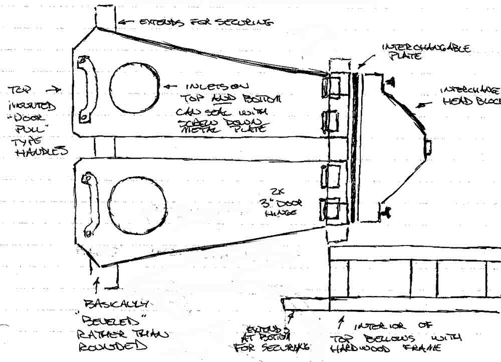
2) A second 'test bed' bellows will be made up (as seen in the illustration above).
- Measurements for this bellows will be determined by taking a theoretical model which is able to produce roughly 1500 LpM. The desired working air volume is actually 1000 LpM. Numbers and images from Jens suggests a true working efficiency of about 2/3 theoretical is likely (assuming good design). Working from more theoretical and experience proven volume requirements, our current run of furnaces work best at roughly 500 to 800 LpM.
- The sides of the bellows will be flat surfaces. This allows to hold the bags in place with metal strips held with screws. This permits easy modifications to the interior of the bag and plates if required.
- The bellows plates will be cut and fitted with intake holes on both top and bottom. In use, either side can be sealed using a metal cover again screwed into place. In this way the difference between top and bottom mounted air valves can be compared. Physical mounting systems for the bellows, and how this relates to operator strain can be compared. An extension of this is further recording of the related debris fields.
- The distance at hinge point of the bellows will be greatly increased, at least double the current measurement. This will allow the installation of two door type hinges on each plate, greatly improving durability.
- The head block of the bellows is a simple boxed shape. To this can be screwed a removable, even interchangeable, exhaust unit. Different types of valves, port shapes and tube diameters can then be attached to measure their impact on flow.
- The handle for the operator will be a wide wooden D type. This will be mounted directly in line with the bellows hinge axis.
Most of the tests involved are primarily static tests, or short applications of human power to the existing air pipe system. There was more interest than I expected in conducting a full smelt using a proven bellows for air. With a proven smelt (bloom production) DARC will have a certain 'all Norse' demonstration possible.
Darrell
(As always, thanks to Skip Williams, who always tells me when I'm 'pissin in the wind' - think Neil Young)


No comments:
Post a Comment