My situation is that I have a very big (!) pile of iron blooms, the result of almost 50 individual smelts over more than a decade of smelting. To date I have only rendered a very few down to bar, and then made even fewer actual objects from the metal.
My problem is that working alone, I just don't have the strength to effectively work these 3 - 10 kg masses!
My current air hammer is a small one. The throw weight is 50 lbs, which of itself would be enough to compress and cut the blooms. The working die surfaces are only 1 1/2 x 4 inches, which most certainly are too small to effectively work any but the smallest of the blooms. More importantly, the starting blooms are irregular half bowl shapes, notoriously hard to hang on to. On such a small working surface, I just can't hold a bloom in place to manage any effective work. (Although my friend and hammer builder David Robertson did have a suggestion to aid that that bears trying.)
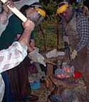
What I have seen a number of people faced with the same problem doing (mainly via the internet) is using a hydraulic powered press to make the initial compaction and cutting of their own blooms. A great example of this is this sequence by my friend Jesus Herandez :
There are a number of variations on the basic design out there. The standard are either a C or an H shaped frame. The pressure cylinders may be placed above or below the working dies.
The advantage of cylinder above is that the lower surface (where you are holding the hot metal) does not move. The hoses are placed safely above the hot metal. The disadvantage is that most of the weight is placed high, a possible stability problem.
The advantage of cylinder below is a more compact and stable unit. The big problem is that the hoses are now below the work - and possibly exposed to hot fragments. Also that the thing you are holding on to is being shifted upwards as it is compressed.
H shaped frames are considerably stronger, and do seem to be the most common.
I had made up some hypothetical layouts and ran them past David. (Trained as an engineer, David knows how to keep my more 'artistic' renderings from falling down - or exploding!) This was my initial concept design:

Now David and I did a back and forth via e-mail. I attempted to refine a possible design, David kicking it apart until it might actually work.
We then met and spent a fairly long (and mentally draining) day looking at parts, visiting a local machine shop, then looking at power packs and cylinders. Near the end of the day we headed back to TSC to purchase the minimum parts that would be required to make a pressure test on a used hydraulic power pack I had purchased at Quad State last fall.
Only to have one of the guys there show us this:
 Price $ 1300. Brand new, totally engineered, self contained with a 6 HP gas engine. The unit is designed so the frame and cylinder pivots in the centre to work in the horizontal position.
Wow. 30 Tons. It works straight out of the box. I can't screw up the power systems.
So David and I did some fast back of the envelope figures. What it would cost to *just buy the parts* for me to build the final layout we had come up with. $1300. That was *not* including a new power pack (and we were having serious doubts the one I had would actually pump enough volume to allow for effective cycle times.)
So I bought the log splitter.
This did turn out to be more rushing around. I had to wait until the next day, download some special members pricing stuff off the internet (turned out not to be straight forward), then make another 45 minute one way drive over to Hanover to pick the crated splitter up.
Now - how to best convert the existing splitter frame system into a forging press. More importantly (as it turned out) into something that would fit and easily operate into the spaces available in my work shop.
My first concept was to do this:
 You can see that this basically keeps the tank and engine system as intended, with an extension that lifts the beam and cylinder up to place the table at a correct working height. The wheels stay mounted, with an L shaped frame that holds the whole thing upright. It would be possible to lift the front legs and move the whole thing around. Obviously a metal shield would have to be placed over the engine, pump and hoses. The hoses also would need to be lengthened about 18 inches - easy enough.
On closer examination, it turns out that the way the existing mounts are designed, that kind of arrangement was not going to be so simple to construct. Too many short pieces welded together, and I'd rather not rely on my welding with something that weighs in at about 300 lbs placed where it would fall on me if it broke.
A number of alternatives were drawn up, often placing components at bad angles - given the placement in the work shop. After several layouts and a lot of looking and measuring of the major pieces, my final design is this one:
 You can see I have swapped mobility for structural strength. The main frame will be made of 3 x 3 x 3/16 wall square tube, in an H shape. The engine is moved below the tank, on to a new mount. The tank and beam / cylinder combination stay exactly as originally designed, but lifted up on to the tubing frame. Although not obvious on this drawing, the supporting frame is now wide, producing a roughly 40 deep by 44 wide base footprint. The two main base legs are of 3 x 3 x 1/4 thick angle, the balance of the frame pieces of 2 x 2 x 3/16. The weight of the press elements now bears straight down the line of the heavy tubing.
Ordering the metal today. I'll keep reporting on this as the project progresses.
(PS - my intent is to describe this whole project as an e-book.)



No comments:
Post a Comment