This may prove to be a bit of a repeat to long time readers, but I wanted to get my (derailed) train of thought recorded. I have been obsessed with this whole thing for a week now.
ONE - Were DID those measurements come from?
 | 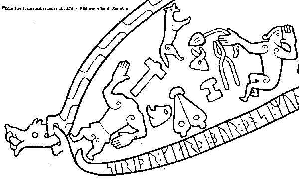 |
Hyllestad Church CarvingCarving | Ramsund Rune Stone |
These are are the only two historic references available to us for what a bellows looks like in the Viking Age. There is not a single surviving artifact (that I have seen or ever heard of). Please assume that I do understand all the problems associated with taking an artist's illustration and attempting to use that for a reconstruction.
The first illustration is a side view in action and gives us a human hand (at 10 cm) to use for size estimates. (Yes I know the illustration also suggests swords are 10 cm wide and heads are the size of beach balls.)
- The working loft (raising the plate) is seen as huge - actually over 90 degrees. You do see that one side is already at maximum when the other is still being exhausted. It turns out that is actually how you correctly move the plates to produce a steady flow of air.
- It shows the operator not actually using any kind of handle, but gripping the edge of the top plate. Again we found this is exactly what many operators will end up doing in action.
- It shows each of the bags composed of each three separate lame sections. These are strengthened somehow so they do not deform under working pressure (either thick seems or some internal bracing).
- a very rough length can be established for the bellows, roughly four or five hand widths (40 - 50 cm). Although the image may be a bit shortened horizontally, the bellows tubes are shown as very long - there would be room for the artist to extend the length of the bellows if he had desired.
The second illustration is more of a diagram, top down, with no figure directly associated to it. It might be possible to associate hand size - but given the figure proportions and related to the hammer scale, this is less likely.
- The relationship of length to width is roughly 2.5 to 1. Considering the length from the first illustration, that suggests a width in the range of 20 cm for each plate.
- The end of the bellows plate that attaches to the head block (where the hinges are) is seen to be very narrow. Applying the scale, it is in the range of 5 cm.
- The ratio between the the top mounted air intake and the width of a bellows plate is roughly 1:3, suggesting a hole size of about 7 cm.
One last piece of important data is the probable size of any outlet tubes. Using the first illustration, the suggestion is about 5 cm. There is however clear artifact evidence here. Ceramic tuyeres from a number of furnace types are relatively common, and most fall clearly into a size of about 2.5 cm internal diameter. Several bellows stones have been found, these too fall into that roughly 2.5 cm measurement.
The Reconstruction
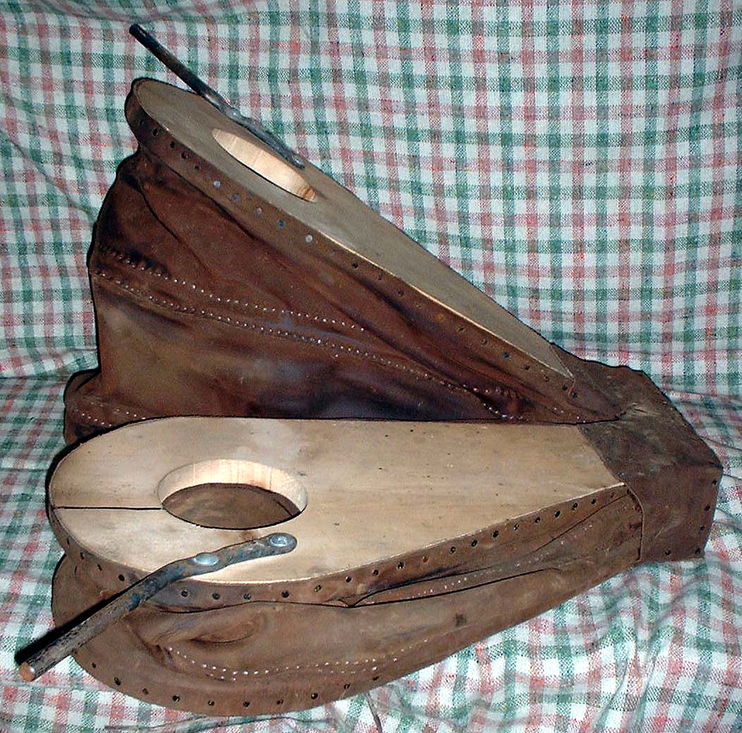 | Reconstructed Norse Blacksmith's Bellows The rough dimensions of the reconstruction are: total length - includes head block: 70 cm total width: 58 cm individual bag length: 50 cm individual bag width: 25 cm individual plate width at head block: 8 cm maximum loft height: 45 working loft height: 30 cm interior of bag at loft: 25 cm inlet valve size; 10 cm outlet tube size: 2 cm minimum internal diameter Photographed against a 1 cm grid |
- The numbers above are measured directly off the bellows (instead of off my blueprints as earlier ones were)
- The 30 cm loft is the working measurement with an operator kneeling and bellows placed on the ground. With the bellows set on a table (like at a raised forge) the working loft drops to about 25 cm.
- When calculating potential air volumes, remember that the loft measurements are on the outside of the wooden plates. The plates themselves are a total of 5 cm thick. The chamber measurement is thus 25 and 20 cm.
There are no valves on the outlet end. Significant air is prevented from being drawn back up the exhaust tube by two factors:
- First the ratio between the inlet and outlet valves. In operation the leather disk that serves as the inlet valve is secured at two points across its mid line. In effect only part of the entire 10 cm space is opened, but virtually no air is pulled back up the exhaust port.
- There is one exhaust port for each chamber, with two pipes leading to a leather box. The box forms the coupling to the single pipe leading to the tuyere. In action this Y shaped arrangement creates a blast effect forward, further limiting the ability of air to be withdrawn back up the opposite exhaust tube. The leather also serves as a flexible coupling, reducing the vibration from bellows operation from reaching the attached tuyere.
More to come on this topic...
There are earlier postings discussing this specific reconstruction:
http://www.blogger.com/img/gl.link.gif2007_07_22_archive.html
http://www.blogger.com/img/gl.link.gif2007_10_28_archive.html


1 comment:
I am trying to have a go at building my own Viking age forge in the UK. I came across your articles about your dual bellows. Do you happen to have any diagrams or photos of how you built them?
Thanks
J
Post a Comment