Air Flow test (or not so much)
This sparked by Neil Peterson's current experimental archaeology paper for the upcoming EAC12 virtual conference at the end of March :

The thrust of Neil's experiment is looking at air delivery pressure, using a smaller 'blacksmith' sized unit. He will be measuring changes over various charcoal volumes.
One of the big variables that significantly impacts the overall functioning of a bloomery iron furnace is air delivery: Air oxygen reacts with the charcoal to produce heat and reactive gases.
- You need to provide a certain volume of oxygen, the bigger the furnace the more volume required.
- You need to insert that air into the furnace, without some pressure, the air does not penetrate.
See : About the Air / May 2013
The DARC team has experimented with the use of two different bellows designs, both extensions of the Viking Age 'twin chamber' design:
 |
| the 'Ubber Bellows' developed in 2005 |
 |
| 'Smelting Bellows' Developed for the Vinland series - 2009 |
As part of the Vinland series of experiments (2009 - 2010) there was a 'test bed' Norse style bellows made. Some details on this unit are available : Bellows for Iron Smelting (the measurements) / July 2018. There were also a set of air delivery tests made : Pushing VA Air - Smelter Bellows Test / May 2012
Modern bloomery iron makers are often criticized for their (common) use of electric blower air systems. The first thing to appreciate is that there simply is a huge amount of physical labour required with any attempt to use any human powered bellows system. Second consideration is that lower air volumes mean less efficient furnace operation, so at least can result in significantly increased overall time required for the smelting process (further increasing labour!)
Air delivered via a blower system (either cranked or electric) provides a constant blast, which is also the case with use of an 'Industrial Age' Great Bellows (see bellow).
Air delivered by earlier human powered systems (bag / pot / drum / twin) all have some element of pulsing air flow. This caused by the break between the fill and exhaust stroke. The Norse twin chamber type does provide a continuous flow, but still there is an obvious cycle of both volume and pressure as the individual chambers are filled and exhausted.
I have been considering how I might mechanically modify the constant blast of our standard electric blower, in some attempt to approximate the delivery from a Norse type bellows. Currently there is a sliding plate (loosely calibrated) that blocks the output of the blower.
 |
| The sliding plate is seen as the first element after the blower output |
I though a second plate, cut with a roughly tear drop shaped opening, could be moved back and forth. This would allow varying the passage of air from 'full' to 'reduced'. Ideally this also would be powered by a small electric motor, geared down to provide one back and forth cycle per second. Attaching a electric power control (like a simple light dimmer switch) would allow some modification of that movement (so mimicking variations in stroke rhythm).
The existing solid plate control allows to adjust total volume to match that produced by potential different bellows chamber sizes. The third variable possible with a human powered system is altering pressure over the course of the delivery stroke. Pushing harder on exhaust stroke would allow for greater penetration of air into the furnace. This is certain to be important in terms of controlling heat distribution inside. The electric blower of course has a fixed delivery pressure.
The Experiment
So it occurred to me I could copy a record keeping method being employed by Neil for his current experiment : video of bellows use and instrumentation. As he instructs, this makes it fairly easy to pull off measurements against time.
As I have commented any number of times, as an 'independent researcher' (and worse, a 'self employed artisan'), funding for instrumentation is limited. Back in 2007, I had purchased a simple wind speed anemometer, a type used by sailors and wind surfers - at the time this unit cost me about $50:
 |
| About 10 cm life size |
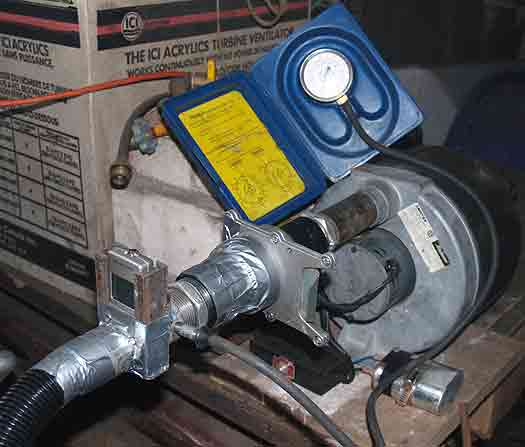
The port for the vanes is 2.5 cm in diameter. The output from my high capacity industrial blower (US Navy surplus) mates to standard 1 1/4 ID threaded pipe fittings (3.3 cm). I made up a fitting that this gauge fits into, so that the casing fits across that pipe ID:
 |
| Recording stet up |
I added a clock to the set up. This both gives an easy time reference, and allowed me to pace my strokes on the bellows to one per second.
I filmed two sets of bellows use. The first was only blocked by the 2.5 diameter of the gauge, but otherwise flowed out of the 3.2 cm pipe. For the second, I fitted the standard forged copper tuyere to the end of the pipe. This tapers from about 3.5 cm (allowing the pipe fitting to screw inside) to 2 cm ID at the delivery end.
I ran each test for about 45 seconds. This allowed me to get the bags correctly filled and attempt to work into a consistent rhythm. In the video clip, I have included a short introduction (for YouTube use), and edited the recording sequence to about 60 seconds each, so some kind of average can be determined.
(The direct link to YouTube is : HERE)
My hope here was to see actual fluctuation over the course of each stroke. You certainly can hear the spinning of the anemometer vanes changing. But as it turned out, the instrument itself is simply not sensitive enough in terms of 'measurement period' to record this.
There is not a lot of new data from this effort. A set of tests on volume applied to a working smelting furnace was undertaken in 2007:
 |
| for the full information : Air Flow Rates |
You see the rough average recorded speed during this new test remains roughly the same as recorded earlier :
46 KpH for no resistance = 375 LpM *
43 KpH through the open tuyere = 340 LpM *
* Aneonometer KpH x 8.17 with 2.5 diameter
Additional Note
Pioneers Sauder & Williams clearly have illustrated (and so many of us have proven) that increasing air volumes in small scale bloomery furnaces impacts the results in two significant ways : increasing bloom yield (so size) and density (so quality). Yes, you most certainly can get some iron from a furnace employing low air volumes.
Given that the 'standard' furnace diameter used here is between 25 - 30 cm ID, that suggests an 'ideal' air volume at :
25 cm @ 590 to 880 LpM
30 cm @ 850 to 1270 LpM
Past smelt experiments here have typically run at 800 to 1000 LpM
The difference between the volume available from the test bellows used above, and the ideal rates (possible with the electric blower), is clear. Through a number of experiments, using very similar furnaces and ore type and amounts, it has been found the yield drops to closer to 15 % with use of this bellows, compared to 20 - 25% with the higher air volumes (for details see the main iron smelting documentation). Typically there is a significant reduction in bloom density as well with the bellows used.
When attempting to re-create a historic process, I believe there are two considerations :
- Does the bellows system being used actually resemble the correct time & culture?
- Does the bloom produced actually resemble artifact ones?
It is in this combination most teams reporting 'Viking Age' process fail. There are a number of past commentaries here about Norse air systems for iron smelting:
Iron Smelting with Human Power / October 2020
Viking Age iron smelting air systems / August 2019
(or search here using : "iron smelt" and bellows)
Actual artifact evidence for Viking Age air systems is almost non-existent. To my knowledge, there are only the two known illustrations of Norse bellows, both of which are related to blacksmithing, not the much larger air volumes required for iron smelting.

Into the Medieval period, you can find a few illustrations of a system also employing a pair of linked chambers:

Variations on this system are seen in illustrations up into the 1700's. Both hand operated for blacksmithing, and much larger water powered equipment used for iron smelting and foundry (cast iron). For a commentary on this specific design see : Early Medieval Twin with Bar Bellows / March 2015
The 'stacked chamber' Great Bellows does not appear until the later part of the Middle Ages - at best. The earliest illustrations of the type, applied to metalworking, date back only to the 1500's. Far too many people are employing Great Bellows for iron smelting - then calling this 'Viking' - when the type is clearly is 500 years later in time.


1 comment:
Yes my own work is producing related results. The Mastech MS6252B is a much nicer unit (USB output is a real boon for work like this) - but vane-type anemometers are problematic. The good ones sample once per second. The poor ones sample less than that. The pace of a bellows has a minimum driven by its design (the flap-valve must be kept closed) but that runs 60-90 beats per minute. So to model the changes in the flow requires a higher sensitivity than any vane-type anemometer I have found.
A pitot tube type or a temperature differential type is likely a better choice. The Omega HHF1001A will do 4 samples/second which does seem better than most.
I do think though that the float tube with a visual reading from video (allowing 30 samples/sec) is where we need to go but the floats I am working with need to be sub-1g in mass which is problematic. More design is required
My talk is 3pm on Mar 29 at EAC (and will be posted on youtube and will remain up there after the conference). Please do join us. https://exarc.net/meetings/eac12
Post a Comment