Showing posts sorted by relevance for query "towards an Icelandic Smelter". Sort by date Show all posts

Tuesday, October 07, 2008

Thanksgiving / Hals setup

Taken with the earlier discussion on the possible layout of the Icelandic smelter at Hals:
This is was the situation at the smelter work area at the beginning of the week. You can see that our last (June 08) clay cobb smelter remains in excellent condition. By intent, I had set up the area with our working smelter to the right side. This was so that a second smelter could be installed to the left hand side of the block retaining wall.

Next is a simple plan view of the existing situation with some of the significant measurements, with a theoretical layout of the Icelandic smelter indicated. I have taken two of the available rail road ties and used these to block in the 2 m x 2m size. On the actual above ground sod construction, this would be a log crib. With the length of the ties actually a bit more than required (and lots of stones!) I set the rear dimension using a row of rocks. By removing three stacks of the retaining wall blocks, I end up with about the correct opening for the front V of a working area leading back to the smelter front wall. Measuring from the current work surface to the tops of the two rail ties, you end up with about the correct height proposed for the Icelandic construction.

the next drawing is an plan view of my proposed set up for the Thanksgiving smelt as it overlays the existing area. As outlined in the last posting, Work Dynamic is the primary thing being explored in this experiment. The position of the hand powered bellows is indicated, and will be blocked in with a plywood cut out for this smelt. The space between the V of the concrete block walls is the length of a standard brick (about 25 cm).

After much grunting and groaning (about 6 hours worth).
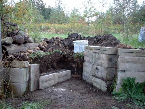
You can see in the photograph that I have cut back the bank to create the V shape work area. The concrete blocks have been used to secure the walls. I suspect that in the historic smelter, these could be a combination of wood (towards the front) and stone slab (at the smelter surface). Our own past experience has shown that any wood within about 40 cm or so from the smelter wall will certainly catch on fire from the radiant heat. At this point I had to scrounge a few more blocks for the left side, so the top surface has not been copletely packed or leveled. As usual for Wareham, the larger rocks (about head size) seen on the left were of course just sticking out an inch or so from my digging lines! As of today (Tuesday 7 AM) I have not actually cut down the cylindrical hole for the smelter itself, which is marked by the plastic pail.

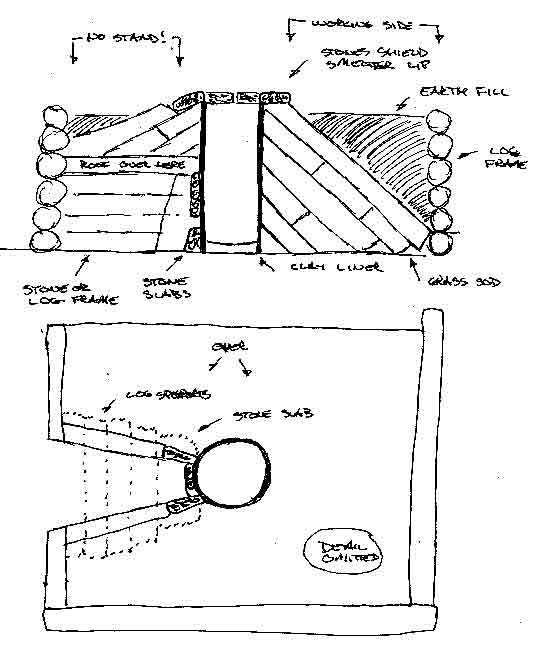
The next illustration is a section through the centre of the smelter roughly S-N. Our standard Norse Short Shaft smelter construction will be used. You can see that it comfortably fits into the earth banking, with its top about flush with the upper work area. One overall question that remains is how to construct the area of the smelter that will be exposed to open air (tap arch, tuyere and the 'heat zone'). Given the relative scarcity of clay in Iceland, I suggest that the historic smelters would have used stone slab with an inset clay bellows plate construction.

The last drawing is a section (cut E-W) I have laid out the working position of the current smelter bellows. Oour tested angle of 23 down for the tuyere is extended along the length of the bellows (about 100 cm) plus the length of our normal ceramic tuyere tube (30 cm). This is shown with the tuyere inserted at 5 cm proud of the smelter interior wall. If the blow tube method is undertaken, the whole workings of the bellows and tuyere would be moved back about 10 cm away from the front edge of the smelter wall. Michael Nissen normally uses a less pronounced angle on his smelter set ups, so the combination should retain a correct working height for a potential bellows operator.

Sunday, October 05, 2008

Thanksgiving at Hals in Wareham (1)

This is a fairly long posting, expanded from a recent set of e-mails.

There has been some discussion (Kevin Smith / Ken Cook / Neil Peterson and myself) of the framework for the Thanksgiving smelt. For those keenly interested, this will be at Wareham Sunday October 12.

As regular readers may remember, the DARC smelt team is working towards a full reconstruction based on the evidence from the Hals site in Iceland. The excavation work is being done by Kevin Smith (reference : 'Ore Fire, Hammer Sickle : Iron Production in Viking Age and Early Medieval Iceland') An earlier discussion - 'Towards an Icelandic Smelter'.
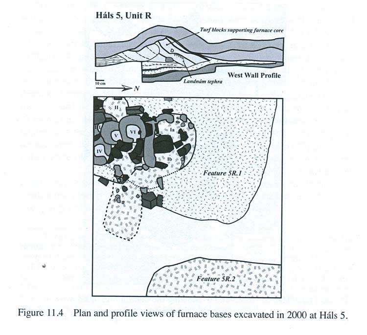
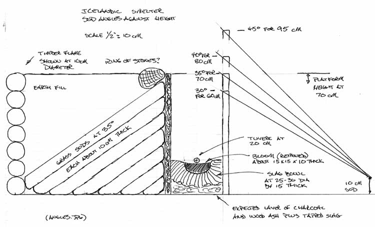
Possible layout for the furnaces at Hals based on remains.

There are a number of individual elements that go towards the full reconstruction:

Sod cone in a log frame construction
Hand powered bellows
Use of thin clay / marl liner on interior
Working down a narrow slot
Tuere above tap arch set up
Stone slab front construction (?)
Use of 'bellows plate' (?)
Use of primary bog ore material


The sod construction represents a major logistics challenge at this point. We need a skid of grass sod (hopefully donated). Time is too tight to set this up for this Thanksgiving. I also think there are a number of other pieces to work up before we go that full construction. We can certainly use an earth banked design which will allow us to test a number of the other elements.

Hand powered bellows is almost a party trick at this point. A full test is more about labour organization than air delivery effect on the smelt. We should get some solid delivery numbers on the new test bellows. This can be done as a simple working test as was done last June, using multiple operators and an averaging aneomometer. Frankly, I'm sure that new bellows unit will give us the required volumes, so this is largely a work dynamic more than technical issue. (see earlier posts)

Use of the thin liner should represent a major test on its own. The simple way (see below) would be to dig a cylinder into our pond earth bank for the smelter, then line the dirt with the thin clay. We will have to substitute straight ball clay for marl - as we just can't GET any marl / 'glacial blue clay). I did read in Pleiner (someplace?) about furnaces that were simple cylinderical holes cut into the ground near the edge of a natural bank. Then lined with a thin) layer of clay as fire proofing. (I think these were English / Anglo Saxon??) The evidence from Hals does not appear to give us either the thickness, or mixture of this suspected clay liner. Kevin Smith has suggested 2 - 5 cm. I suspect you would want to use the horse manure cobb here.

The work dynamic of the Icelandic is the easiest thing to work on right now. Ken and I talked it over, and we think we can 'fake' this out by digging a key hole into the side of the pond bank (more details below). This would let us use the upper ground level as if it was the top of the sod construction., blocking out the 2 metre square working platform. Now this would require us to undertake all the physical adjustments to the smelt bowl working down a roughly 1 m long slot. I think we should also fake the position of a man powered bellows by placing a plywood cut out, but at this point still use the blower air system. This should definitely be one of those 'rake the sand' experiments to look at work and debris patterns.

The major shift for us is the placement of the tuyere directly above a small tap arch. Michael Nissen from Ribe uses that rough layout all the time on his smelters. I'm not really expecting any big problem here. (see above)

Now, we did mess with the stone slab construction for the Thanksgiving and Fall smelts of 2007. The first of these we did try to use the 'blow tube' style tuyere (tuyere set back from blast hole), but with poor results. The use of a stone front on the smelter (or entire stone construction) has been tested to success. My own interpretation of the layout from Hals leads me to believe you would want to(ideally) construct the smelter with a stone slab set above a clay bellows plate. Our own tests certainly suggest that any stone used in this fashion will bear significant and distinctive patterns. Kevin Smith has reported "We do have a small number of spalls with slag that could make sense from a similar use.", from a discussion on our results from the October 2007 smelts.

What about the use of a separate clay bellows plate? This represents both an archaeological question at its core. Again, there appears to be no specific artifact evidence, but this is balanced against the relatively fragile nature of these plates. Does the evidence indicate STONE used as the front section of the smelter around the tuyere? . What about the use of a separate clay cobb 'plate'? A number of smelts (mainly Nissen) have shown that a roughly 15 x 20 cm by 2 cm thick plate of dry horse manure mixed with clay works extremely well.

The third piece of this method is the set up with the tuyere actually sitting proud of the smelter wall. I did use the combination of bellows plate (thin plate around tuyere entry) with blow tube set up at Smeltfest 08 for two smelts with good results. Also watched this done three times in Denmark. So taken together, I'm pretty sure we can get this to work.

We do need to tweak the mix on the DARC Dirt. Due to bad communications (and poorer math!) the actual iron content of the first round of test materials was really on the low end. It did match the St Lunaire samples, but ideally I'd rather bump up the iron content to something richer and more likely to give higher end yields.
Given time and supplies, it might make more sense to use a richer ore body for this next experiment. We also should try to match the ore content from Hals if at all possible.

SO

Trying to keep with the wisdom of not changing 5 things at once (!!) I propose the following for the Thanksgiving smelt:

1) Overall set up is a totally earth surrounded smelter at the end of a slot - with the layout similar to those at Hals (see below)
2) Use a thick walled clay cobb furnace structure.
3) Set up the work area with a fresh sand base.
4) Use a known pure ore (the taconite likely)
5) Fake out the location of the hand bellows, but use the electric blower for air

A) Use either stone slab or bellows plate construction
B) Use blow tube arrangement for the tuyere (which can quickly be modified to our normal insert tuyere if required.

This suggests to me one minor (number 1) plus two major changes (A / B). I have worked both A / B, and 1 is more a modified work dynamic than an actual major change.

The set up of the furnace with only a small tap arch down a slot certainly leads to a top extraction. To that end we should aim for a 3 - 5 kg bloom.

(More on Construction in the next Post)

Tuesday, April 14, 2009

Winter Weathering - Icelandic Destruction!

Question : How might an Icelandic styled smelting furnace survive a winter?
Answer : Quite poorly - to its destruction!

Long time readers know that my team here from DARC is working towards a full scale re-construction of an Icelandic styled iron smelter, based on Kevin Smith's excavations at Hals (from the Viking Age)

An interesting piece of the puzzle was seen this spring, when the snow finally came off here in Wareham. Now admittedly this is Central Ontario, and this winter was unusual. There were at least three separate snow dump and thaw cycles this year. Almost much snow as a typical year came down from early November through to mid December, followed by a thaw that melted most of the ground cover off just after Christmas. This was repeated in January, with a finial dump which is still not totally melted at the point I am writing this in Mid April.

The result is even more freeze and thaw damage than is typical, and the two smelters still standing in our working area clearly demonstrate this. Both were covered with a metal drum to prevent direct rain damage, and to prevent snow from filling the shaft.

First is one of our standard 'Norse Short Shaft', furnaces, half earth banked. This furnace was built and fired in early October last fall. The first image shows the rough condition of the structure at the start of the bottom extraction process. The second shows considerable spalling off of the front wall as winter damage. I estimate that the furnace has lost almost 50% of its thickness of about 8 cm. It should prove possible however, to simply patch and continue to use this furnace, as there is virtually no damage at all to the inner, sintered, surface of the shaft.


Compare this to the condition of the Icelandic pattern furnace, built and fired in early November last fall (and set about five feet from the other one).
This furnace has walls only 3 cm thick roughly 1/3 as thick as the other smelter. When the furnace was used, the whole exposed front face was badly cracked, so it was decided to simply remove the segment above the bellows plate and tap arch when measurements were being made (image to left). Over the winter, the entire structure disintegrated, and the soil surrounding the cylindrical shaft has slumped into the resulting hole (image to right). The circle of stones originally surrounding the top of the shaft have come to rest on a layer made up of broken, sintered furnace wall from the upper part of the shaft (image at centre).


The supporting structure at Halls was made up of stacked layers of grass sod, which certainly would have been more stable than the loose earth backing used for our initial test furnaces. The fact remains that the thin clay cobb lining, at best partially sintered, would be unlikely to survive the riggors of an Icelandic winter. This may have a bearing on the remains found at Hals, since at the very least it suggests an individual furnace structure would only prove usable, without heavy rebuilding, for any more than a single summer season.

Friday, September 28, 2007

Towards an Icelandic Smelter (1)

(As background - Early Iron 4 was canceled due to lack of organization.
and I had already set aside time for it. So on short notice I decided to
run another smelt here at Wareham)

Dr Kevin Smith and I have been discussing the work he has been doing
excavating a Viking Age iron smelting site at Hals in Iceland. The
details can be found in his article 'Ore, Fire, Hammer, Sickle: Iron
Production in Viking Age and Early Medieval Iceland'.

A long range plan is to work towards a full reconstruction smelt using
the Hals excavations as the prototype. In brief the construction is a
conical stack of cut grass sod strips contained in a box frame of
timber. This whole construction is roughly 2 x 2 m and stands about 1 m
tall. The space between the cone and the box is leveled off with earth
for a working surface. The shaft of the furnace is cut down into the
sods, then lined with a relatively thin (3 cm) layer of clay like
material. The tuyere area is made up of stone slabs, with a 'blow hole'
method used to introduce the air. Evidence strongly suggests a top
extraction.

Taking some information provided by Skip Williams from his experiences
working (primarily) with Micheal Nissen (from Ribe) at the last European
Iron Symposium:

The blow hole has a thin plate of material used in those areas of the
furnace around the tuyere that are subjected to the greatest
temperatures. The thinner plate around and especially above the tuyere
opening allow the heat to bleed off the surface and keep the plate from
melting. (This opposed to our current thick walled furnaces that
withstand erosion every smelt.) The tuyere itself does not fit tightly
into the smelter - or protrude into the inside of the furnace. (Our
current method does both of these.)

This blow hole method has proved successful (Nissen and Williams) at lower air volumes - in
the range of 300 litres per minute.
As the bellows tube does not extend into the furnace, there is minimal
damage to the tube. (In essence there is no true tuyere - just the
nossel of the bellows).
The opening for this bellows tube is larger than the tube itself. In
practice Skip reports this produces a venturi effect to increase air
flow. It also allows the operators to see directly into the interior at
the developing bloom. Any surplus slag will flow off well before it
clogs up the air blast.

I have decided to run the Thanksgiving smelt as the first test towards
the full Hals prototype:

The main difference here from our last smelter is the construction of a
stone slab front and use of the blow hole method. The overall
construction will remain the proven thick walled clay cobb set as half
buried in the earth bank. The tuyere / bellows tube will again be the
ceramic tube with air via the current vacumn blower. This blower can be
throttled back to the lower air volume.
There is plenty of charcoal on hand, most likely using the pre sized
material that the Wareham Forge purchased in the spring (to save labour).
As the evidence from Hals suggests a high iron content bog ore was used
(very little slag produced) I'm suggesting use of the hematite grit as
the ore. Carbon control may be a problem, but the smaller particle size
may prove a good fit to a reduced air volume.

In truth this amounts to THREE changes to our process: Tuyere / Plate /
Air. I don't anticipate too many problems from the use of the stone
plate construction. Air can be quickly modified if required. The use of
the blow hole rather than our standard insert tuyere is the main
modification here.

Still there is a good chance (I'd say at least 50 / 50) that the smelt
may not result in a working bloom.

(Stay tuned!)

Thursday, November 01, 2007

Icelandic Smelt Two (report)

Stone Slab with Low Air

As was mentioned earlier, the DARC fall smelt was originally intended to follow on the development of an Icelandic style smelter.


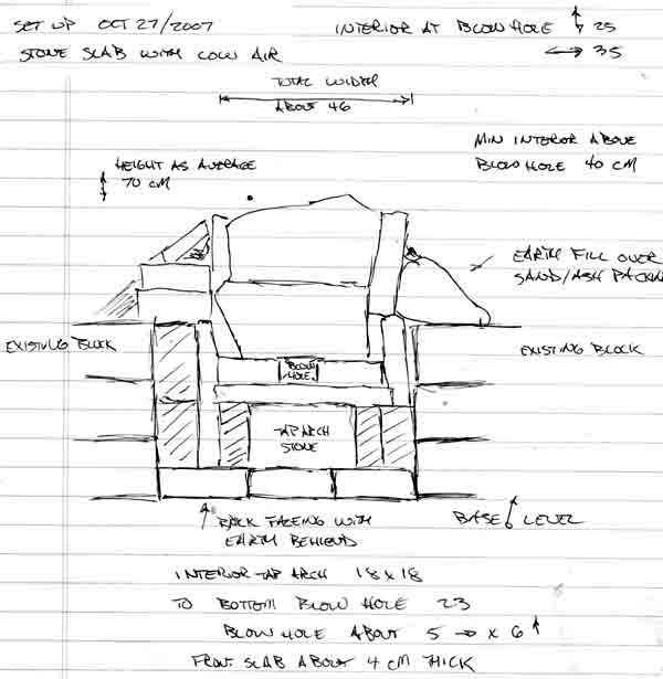
Front Elevation Drawing

On Friday, Darrell, Neil Peterson and Ken Cook worked on preparing the site and building the furnace. After a fairly wide ranging discussion, it was decided to work towards two experimental objectives:
1) Running a smelt with lower volumes of air.
2) Build the furnace using a stone slab construction method.

The all stone slab construction was an extension of the Thanksgiving smelt, which had just the front section of the smelter made of stone. It also was a return to our very first group smelt (in spring 2002). The material on hand were relatively thin and randomly shaped pieces of mica schist. Despite some concerns about how water can create some potentially explosive effects on this stone when it is subjected to high temperatures, the material once again stood up extremely well.


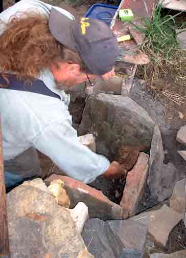
Ken at work sealing gaps with clay

The shape and proportions of the furnace was largely the result of the irregular shapes we had on hand. The overall height of the structure was also limited by the amount of stone available. Ken undertook most of the construction work, fitting the various slabs together as best he could. Considerable attention was focussed on the lower section and the front above tuyere level. The gaps between the slabs was filled with prepared clay cobb and sealed using wet waste clay. Once again the advantages of the straw fill in the cobb was obvious over the course of the smelt. The finished smelter actually most closely resembles the construction suggested for L'Anse aux Meadows.


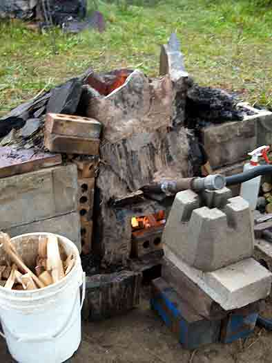
Furnace with tuyere in place - pre-heat phase

The finished furnace was deemed to be the ugliest one we had ever constructed! A large tap arch was blocked out by a nicely shaped stone. It was decided to use a bottom extraction method for this smelt. This resulted in a rather large lower section to the furnace, so a base level of charcoal fines was established. With the height of the tuyere elevated above ground level, but the total height of the furnace about the standard, the effective shaft height above the tuyere was reduced.
Another wrinkle on the construction was a ledge of stone from the piece used to span over the tap arch. The tuyere was positioned so that it came just to the inner lip of this stone. In effect this placed the tip of the tuyere about 6 - 7 in from the line of the smelter interior wall.

Chamber size at Tuyere : 25 cm (front to back) x 35 cm (side to side)
Total furnace Height : 70 cm (random)
Shaft Height above Tuyere : 40 cm (minimum)
Height of Tuyere above base : 18 cm
Tuyere angle : starts at 26 down, latter shifted to 10 down
Tuyere size : standard 2.6 cm ID steel pipe

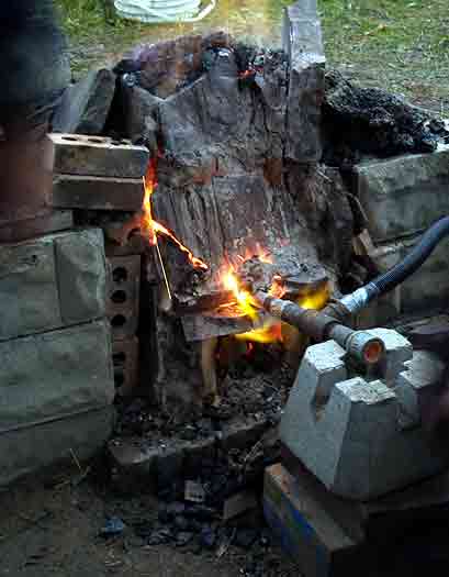
It was expected that the lower air volumes would greatly extend the time required for the smelt. Although better intentions were made, the pre-heat was started at our normal 9 AM, with primary smelt sequence started a bit after 10 AM. As normal, pre-heat was using wood splints, passive at the start and for the last 15 minutes or so using gentle air.

For this smelt, Neil was the iron master, with Ken working as lead hand. Darrell started the recording, with Ron Ross managing the latter half of this task.

It was decided to seed the smelt using the poorer quality Virginia Rock ore gathered last year by Darrel and Vandy. Although this material has proved to have too low an iron content, it was hoped that it would compensate for the lack of slag seen with earlier uses of the hematite grit. It was also expected that considerably less slag would be available inside this smelt with the use of stone instead of clay for the wall materials. In the end it proved we were overly conservative, and production of a suitable volume of slag would prove a problem.

With the lower consumption rates expected as a result of the lower air volume, it was also decided to limit the total amount of ore added. It was expected that this would only allow for the formation of a small bloom. The air volume used over this smelt was about 400 litres per minute - compared to the usual rate employed in past successful smelts at closer to 800 plus LPM. As was expected, the lower air greatly extended the time between additions of the standard 10 litre charcoal measure, which increased from a normal 8 minute average to closer to 22 minutes. The construction of the furnace had reduced the height of the reaction column from our normal 55 - 60 cm to closer to 40 cm. Still the theoretical 'drop time' for any individual particle of ore had been extended from a normal 25 - 30 minutes to double that - closer to 60 - 70 minutes. This was expected to produce problems in carbon control with the fine particles of the hematite grit.


At the start of the burn down phase - note heat effects around tuyere

A secondary concern was the amount of penetration of air into the body of the smelter, again an expected effect of the lower volumes. Several times during the smelt, the depth of the heated zone was measured at tuyere level, This was done by the simple process of inserting a 3/8 diameter mild steel rod held horizontal to the ground through the blow hole. After about two minutes the rod was pulled out, and the colour of the rod used as a simple measure of heat. The rear 1/3 to 1/4 of the rod did not show any visible colour, indicating that the area of the furnace furthest from the tuyere had to be below 600 C. It was hoped that additions of ore would none the less drift towards the ignition area above the tuyere regardless.

Over the course of the smelt, the following totals were recorded:

Ore : 12.3 KG (10 kg hematite grit / 2.3 Virginia rock)
Charcoal : 170 litres + 6 kg ungraded fuel at start
Time : Main sequence = 6 hours

Generally the slower consumption rate lead to a much less frantic smelt sequence. It was obvious fairly early on that less slag was being produced. Although the furnace had been constructed as an 'incontinent' type, little slag was ever observed flowing from the slag bowl (even after the tap arch was opened latter in the smelt).


Neil reaches in with the bloom tongs, the bottom of the slag mass can be seen

Neil undertook the extraction, and was able to grab almost the entire slag mass as one piece. There was little liquid present, and not much remained inside the furnace (generally both bad signs). Kevin Jarbeau and Ken worked the surface quite lightly with the hammers. Almost immeadiately, the majority of the mass split away, obviously only slag. The material remaining was extremely granular and poorly sintered. Even under gentle strokes of the large hammers, it quickly broke into a number of golf ball size pieces. Although we had hoped for a least a small well consolidated bloom, it was clear our product was too fragile to work.

The next day the cold smelter was excavated, with a good photographic record made and representative samples collected. All the slag was collected, and the area was cleaned with the large magnet. The results of this work:

Weight of Slag : 3.5 KG
Weight of Reduced Ore (but poorly or not sintered) : 3 KG
Weight of 'Bloom' (fragments) : 2 KG


Fragments of still hot 'bloom' in place on the stump

Although the general opinion on the day was that the product of the smelt was in fact a high carbon cast iron, I personally had some doubts. In past uses of the hematite grit as an ore material, the results even with high air volumes always had a granular texture and a high carbon content. On Tuesday I attempted to work one of the denser fragments inside the coal forge. Knowing how fragile this granular material would be, the roughly goose egg piece was brought close to a welding heat and very gently worked with a wooden mallet. Even under the lightest of strokes it was not possible to do much more than just push the grains a bit closer together. I was not able to actually forge the material into any kind of solid piece. The end result was just a larger pile of smaller fragments. One piece (about 3 cm wide and about .5 thick) was compressed enough to have a noticeably flat surface, this was taken to the grinder for a spark test. The sparks produced were like those seen from a piece of high carbon tool steel (in the range of 1 % plus carbon content). It may prove possible to forge weld the fragments between two other slabs, but I was unable to work the material as it exists at this point.

Conclusions:

1) The construction method using stone slabs with clay cobb sealing the joints is certainly viable. It is unlikely that the mica schist material would withstand a second firing without heavy replacement of the material at the normal hot zone above the tuyere. The stone in this area exhibits both considerable erosion and also a thick deposit of slag. Both of these effects should remain clearly visible in archaeological remains of this type.

2) The use of lower volume air requires considerable further experimentation to develop a truly successful sequence. As has been clearly demonstrated with both our earlier smelts and those of other experimenters - there is a (poorly understood) relationship between ore type and purity, smelter material and design, fuel preparation, and physical sequence. Those attempting smelts with low air volumes have great difficulty (if able at all) in producing large and well consolidated blooms.

3) In retrospect, it is most likely that both the content and the fine particle size of the hematite grit renders it quite unsuitable for use in any kind of low slag producing smelter. The extremely low silica content of the ore means that the formation of slag must come almost exclusively from the melting of the smelter walls. Although good results have been attained with this material in past smelts, this has always been inside those furnaces that have suffered considerable internal erosion.

Monday, January 28, 2008

Bellows Reonstruction 3


This is a detailed image of the Ramsund Rune Stone.
The image is loading directly from its internet source - the University of Pittsburgh.


Two short summaries on the the historic illustrations used as a basis for my bellows reconstructions:
http://www.pitt.edu/~dash/sigurddoor.html
http://www.pitt.edu/~dash/sigurdstone.html
Both by Professor D. L. Ashliman of the University of Pittsburgh


The core members of the DARC smelt team (Neil, Kevin, Dave and Ken) where up over the past weekend. We discussed what we are learning, what we have done, and what direction this year's campaign at the smelter should take.
The main thrust will be work towards the reconstruction of the Icelandic grass sod smelter. At present we have to pieces of technical work to refine. The first (not dealt with there) is the creation of a workable bog ore analog. The second is to finally get an effective bellows design.

Considerable background help on this has come from Jens Jørgen, who works at the living history side of the Heltborg Museum in NW Denmark.
Unfortunately the museum web site does not seem to detail the iron age farmstead reconstruction where Jens works as blacksmith and also smelts iron.
He has posted up a number of images related to the iron demonstrations and his bellows specifically.

There is one primary reason why the current bellows reconstruction (detailed over the last couple of postings here) does not work as expected when applied to an iron smelting furnace. The actual air volume produced is significantly less than the projected theoretical volume. (It should be noted that this bellows design and construction has proved very effective for blacksmith's forges and for bronze casting.)
Neil has pointed out that even small changes in the measurements can produce large variations in potential air. Using the new set of measurements from the bellows directly and he crunched the numbers. The highest possible *theoretical* volume produceable by my reconstruction is in the range of 500 - 600 LpM. So with the * actual * measured volumes at closer to 150 - 200 LpM - what the heck is going on?

So I did what I should have done at the start of this - I dragged the bellows out and set it up inside my (heated) studio. I pumped and measured and took photographs. I looked and pumped and measured some more. Then I thought about it and looked again.

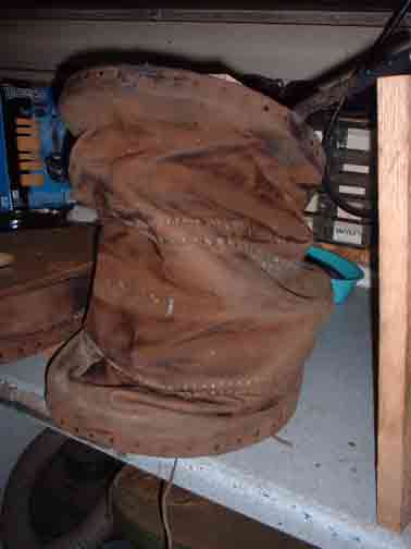
When I had initially made the reconstruction blueprints, I had tried some body positions for the operator - just faking it. I based things like handle positions and most importantly - the amount of lift - based on that. This suggested to me that the maximum extension of the top plate could be 46 cm. I cut the fullness of the leather bags to allow for that elevation. There are three lens shaped pieces to the bag, each about 15 cm at the widest point.
In actual use however - what the operator * really * does is raise that plate to only 30 cm (less when the bellows is mounted at waist height on a forge table). The net effect is that one complete leather section is not being used. Since there is more bag that required, the whole bag collapses sideways and crumples - effectively reducing the amount of air inside. On the exhaust stroke - that extra leather has to be compressed - and so the plate can not be depressed as far as it might be with a loss of volume again.

My only excuse here is that I'm usually the one on the bellows - or have my head stuck inside the smelter - or trying to organize a 3 - 6 person team - or running back and forth to the workshop trying to find tools...
The operator of the bellows can't actually SEE this folding and distortion of the bag. Its only really obvious from just behind and at the same eye level as the bellows. As an uninvolved observer. We also gave up on use of the small bellows after I met Lee and Skip the first time and they told us about the correct use of higher air volumes.

On top of that, I think the leather I used may also be a bit heavier than required. (At the time I had access to a large amount at a good price.) There are wire stiffeners along the double seam lines - but these would be better replaced with metal rod hoops (like 1/4 round rod).
2008 year experiments


'Test Bed' Double / Twin bellows for iron smelting

1) Neil has ordered a copy of the small blacksmith's bellows for his glass bead furnace project. This will be made up using the current physical measurements, but with two important changes.
- First the bag will be cut with only two leather lames - giving a maximum loft in use of 30 cm. This will reduce the folding of what is just unused leather surface. The wooden frame will be made up, and then a fast test bag will be made up out of taped plastic. This should allow for a fast test series to be made to measure the air volume with the shorter bag.
- If this test proves effective, then the bags will be made up using a lighter (likely deer skin) leather than has been used on previous versions.
- The centre seam will be fitted with a more rigid metal hoop than has been used in the past (at least 3/16 if not 1/4 inch round steel rod).
Taken together, this new unit should allow us to record more accurate numbers for the possible use of the historic patterned bellows in smelting.

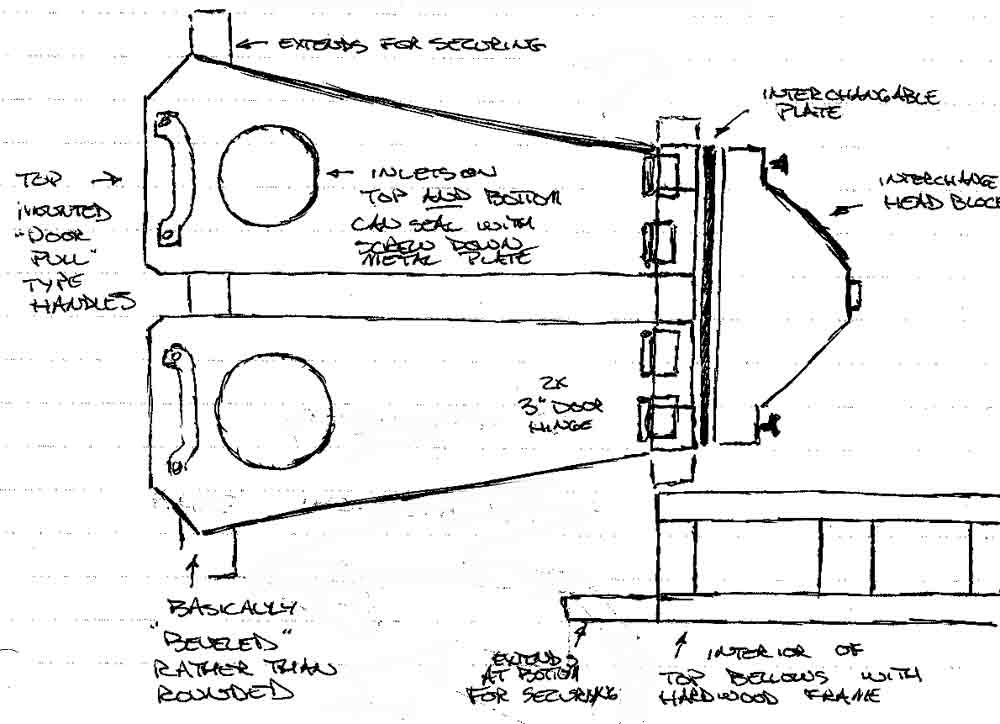
2) A second 'test bed' bellows will be made up (as seen in the illustration above).
- Measurements for this bellows will be determined by taking a theoretical model which is able to produce roughly 1500 LpM. The desired working air volume is actually 1000 LpM. Numbers and images from Jens suggests a true working efficiency of about 2/3 theoretical is likely (assuming good design). Working from more theoretical and experience proven volume requirements, our current run of furnaces work best at roughly 500 to 800 LpM.
- The sides of the bellows will be flat surfaces. This allows to hold the bags in place with metal strips held with screws. This permits easy modifications to the interior of the bag and plates if required.
- The bellows plates will be cut and fitted with intake holes on both top and bottom. In use, either side can be sealed using a metal cover again screwed into place. In this way the difference between top and bottom mounted air valves can be compared. Physical mounting systems for the bellows, and how this relates to operator strain can be compared. An extension of this is further recording of the related debris fields.
- The distance at hinge point of the bellows will be greatly increased, at least double the current measurement. This will allow the installation of two door type hinges on each plate, greatly improving durability.
- The head block of the bellows is a simple boxed shape. To this can be screwed a removable, even interchangeable, exhaust unit. Different types of valves, port shapes and tube diameters can then be attached to measure their impact on flow.
- The handle for the operator will be a wide wooden D type. This will be mounted directly in line with the bellows hinge axis.

Most of the tests involved are primarily static tests, or short applications of human power to the existing air pipe system. There was more interest than I expected in conducting a full smelt using a proven bellows for air. With a proven smelt (bloom production) DARC will have a certain 'all Norse' demonstration possible.

Darrell

(As always, thanks to Skip Williams, who always tells me when I'm 'pissin in the wind' - think Neil Young)

Friday, September 20, 2013

Building an Icelandic Iron Furnace?

 Some questions concerning a possible DARC build of the Icelandic Iron Furnace - as suggested by Kevin Smith's work at Hals...

Richard  wrote:
 

-- what are the archeological dimensions I should be aiming for?
-- am I burying it in a bank or should it be free-standing?
-- given the strong prevailing winds here, should I be looking to place it in a sheltered location, or would careful orientation help create better draw
Suggested build of the original Hals Furnace

1)Link to the full report on the Hals furnace:

The full construction is  a cone of sod roughly 2 meters in diameter, standing roughly 70 cm tall. There is a 30 cm diameter cylinder down the centre. The suggestion is that this cone was surrounded by a box made of timber (alternating logs?) - with the gap between the timber and the sod filled with earth.

2) In effect the construction above is like a free standing bank. The box of earth makes a stable work platform on the top.
One important question is :
"How wide does the sod band need to be."
In use, the sod is in effect taking the place of the thick clay cob walls we have been building to date. The grass roots are creating the stability - during the firing process. The interior wall of the cylinder had a thin (3 cm suggested) layer of clay like marl as a fire proof coating. The fact that the stacking of the sods creates a series of diagonal lines - running downwards away from the interior - is going to keep hot gasses from seeping out of the grass layers.

A team from Iceland, under Margrét Hrönn Hallmundsdóttir, had run a version of the Hals system last year. Margret has worked with Kevin Smith, and she and I did converse a fair amount before her experiment (her first full iron smelt).
http://www.warehamforge.ca/ironsmelting/HALS/angles.jpg
The furnace they built (at least from the photos), was more a square, flat layered stack of the grass sods. They also made some other departures from the archaeology at Hals. I thought the main one was that they built a chamber of stone blocks for the bottom third of the furnace (basically square). The construction they used was using the sods more like flat stacked bricks.

It has occurred to me that we might do a first test by either partially earth banking the construction - or putting the whole inside a smaller plank constructed wooden box.
The first would allow us to undertake a top extraction - which is suggested by the Hals evidence (slag bowls in place). The second would be simpler using a bottom extraction.
Something to take a look at would be the way the team from Tranamo Sweden group had  built a semi portable demonstration furnace. They had used a cylinder of fire brick held in a 45 gallon drum - this surrounded with a wooden box that they used earth to stabilize.

At Heltborg, Denmark, 2008

On alignment to the wind:
It might be nice to have the wind going from our backs across the front of the furnace - or from side to side. At Wareham the prevailing winds go from the rear of the smelter towards the workers. This only occasionally pushes the heat into our faces (singed beards). In terms of providing air blast - it would only be the rare day this would really be useful. A bellows or blower system is still in play here.

DARC has undertaken a number of smelts in a series leading up to a full reconstruction of the Hals Iceland system. You can find this work documented on the full Wareham Forge IRON SMELTING web site

Wednesday, October 28, 2020

65 at 65

An iron smelt event

October 31

Wareham

I have been casting around for some direction to head with the long set of individual iron smelting experiments, now after the better part of 20 years of undertaking.

Start of the insanity : L'Anse aux Meadows - Summer, 2001

 Starting with that initial week long research workshop at L'Anse aux Meadows NHSC for Parks Canada, the first years were spent just figuring out how to even get any iron at all (!) I dragged members of the Dark Ages Re-Creation Company into the madness. It would not be until my 6th attempt (# 4 with DARC) in Fall of 2004, that there would actually be a workable iron bloom produced.

I was lucky to fall in with Lee Sauder & Skip Williams, and Mike McCarthy. Mike would boldly start the original 'Early Iron' symposium series, the four of us forming the 'Gangue aux Fer'

Sauder / Williams / McCarthy (me in the back) - Early Iron 1, 2004

Lee would launch an annual series of workshops at his home base in Lexington, Virginia, running 10 - 14 days every March from 2005 through to 2011. At 'Smeltfest', furnaces were built and fired daily, investigating the individual variables which effected the success (or failure!) of bloomery iron production in small scale furnaces. Over those years there would be a number of additions, with Shelton Brower and Steve Mankowski (of Colonial Williamsburg) becoming other core members. Another significant accomplishment would be the development of the 'Aristotle' re-melting furnace, which we tested extensively in 2009.

Brower / Sauder / DIck Sargent / Williams / Mankowski - Smeltfest 2009

Here at Wareham, the experience and knowledge gained from all this trial and error experimentation would start to be applied 'backwards' towards specific historic historical prototypes, potential equipment, and possible methods - most specifically to those from Northern European / Viking Age archaeology.

The first specific archaeological series was with Kevin Smith, based on his excavations at Hals in Iceland, with experimental work starting in October of 2007. A total of 8 full smelts were undertaken in this series, extending through to October 2016. 

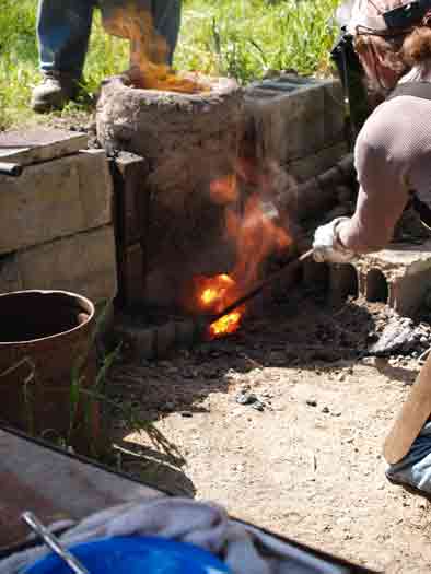
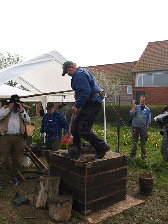
Neil Peterson, Icelandic grass sod furnace - Hals #8, 2016

Part of the reason that the Hals series ran so long is that the DARC team was approached by Parks Canada in 2009 about running a full scale re-creation of the iron smelt by the Norse at Vinland, as a public demonstration event in 2010. A total of five experimental smelts were ran in this initial series, to be followed up later by another demonstration event in 2017. Both these smelts at L'Anse aux Meadows NHSC would use all circa 1000 type equipment, other than required safety equipment.

Mark Pilgrim (LAM) / Dave Cox (DARC) / me, Vinland #5 (at L'Anse aux Meadows), 2010
Other experimental series work has included two projects from early Scotland :

- Turf To Tools at the Scottish Sculpture Workshop (Lumsden, Aberdeenshire). This based on their local Pictish history (so post Roman / pre Viking). This included one test smelt here in Canada, then four at SSW, in 2014. The second segment of the project was in 2016 and was composed of another three smelts in Scotland. There was a third segment planned to complete this overall combination research and artistic project for September 2020, but COVID lead to postponement. 

- Work at the Scottish Crannogg Centre, based on Early Celtic Iron Age. This series has included one test at Wareham, staff training on site in Aberfeldy in 2016, then a demonstration smelt in 2017. 
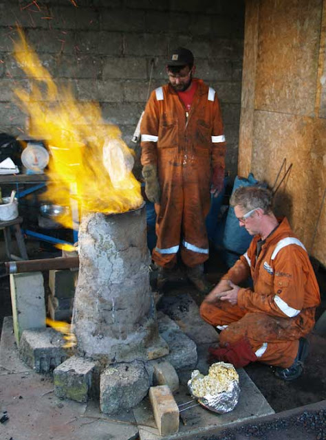
Uist Corrigan / Eden Jolly (SSW), T2TA, 2016

Along the way :

- The development of an primary bog iron ore analog, based on the physical characteristics of the natural material found in excavations at L'Anse aux Meadows.

- A number of full scale tests of various historic human powered air systems. (experimentation possibly remains here.)

In total, to date I have personally mounted  over 85 individual iron smelts.  The majority have been intended to answer specific experimental questions, or to accumulate enough working experience to allow useful data to be gathered. There have been a significant number undertaken as public demonstrations, at international symposiums, or as training sessions for students.


'What's next?'

When my long time collaborator and smelting partner Neil Peterson was up to Wareham last week (for a day rendering bloom pieces into useful working bars), he asked what the plan was. The last experimental smelt was the 'Bones' test in June. Although there could be a continuation there, truthfully I don't feel there is much insight to be gained that would be worth the investment in materials, time and effort. I had started some background on early Irish bowl furnaces, but not enough at this point to realistically frame a working experimental series based on this. 

We considered the current test furnace, the stone block, built for a second Icelandic research project over 2019. This furnace has been fired four times at this point, and had suffered some structural damage on its last use (course over Thanksgiving).  Given the shift to colder late fall temperatures (below freezing at night, mid single digits daytime) and the general lack of a clear direction, I decided to repair this furnace for one use.

Condition of the stone block after Oct 11 smelt. The red line is where the original lintel stone (above the extraction arch) had broken out.  

I turn 65 just days after the already scheduled Samhain Iron Smelt, set for Saturday 31 October. 

With tongue in cheek, Neil said " 65 in 65. You could smelt 65 kg of ore. "

Now, the largest volume smelts I personally have ever done have been with 45 kg of ore ( Smeltfest 2005). These also resulted in some of the largest blooms, into the range of plus 20 kg. Attempting 65 kg could increase everything by 40 %, importantly the amount of charcoal and raw working time ( * ). Bloom yield also increases steeply with larger ore amounts. I'm not really sure the furnace on hand would contain what likely would be such a massive bloom!

Past use of this specific furnace has shown it will accept alternating 2 and 3 kg charges at the end (this against standard 1.8 kg charcoal amounts, burn rate averaging 14 minutes.) The stone mass has been found to take significantly longer to come up to working temperature (in the past about 2 + hours). With our normal roughly 30 kg ore amounts, the elapsed time of the main sequence has been in the range of 5 hours.That all suggests an attempt at a 65 kg smelt would add about another 3 - 3 1/2 hours to the main smelt sequence, suggesting a total experimental time (first pre-heat to final extraction) of 12 1/2 hours. ( ** ) 


Just recently, the metal bands on my cut wooden barrel slack tub failed. One of the 'mystic' things here is that tub has never been emptied since I set up the forge at Wareham, back in 1990. (This included some water gathered from the point where Black Duck Brook mixes with the ocean, just downstream from the Smelter Hut at L'Anse aux Meadows.) In the process of replacing the bands, 30 years of accumulated iron forge scale was collected. This material, 2.5 kg, had been added to the analog mix being made in preparation for Saturday's smelt. This material is still drying, but there should be at least 30 - 32 kg of analog.

As I have mentioned before, the region around Wareham does not contain any naturally occurring iron ore. This has meant over the years having to use a wide range of types (and quality!) of ores, perhaps more than any other long working team :

- primary bog iron ore - Newfoundland / Denmark

- 'Lexington Brown' limonite - Virginia

- industrial taconite - Ontario / Scotland

- hematite grit - Quebec

- red iron oxide as analog

- black iron oxide as analog

It has occurred to me that I do have plenty of the other ore types we have worked with here over past experiments. Right now I have a good large amount of variable quality Lexington limonite, including a 'smelt's worth' already roasted an partially broken for size. There is also about 40 kg of hematite grit remaining. 

This suggests starting with 6.5 kg of the limonite (pretty much were we started, and a tribute to Lee and Skip), followed by 6.5 kg of the hematite (which actually was the next ore body which we worked with, easily available in Ontario back at that point). The limonite, which I gathered, does tend to be on the lower iron content side. This should be balanced with the hematite, which if anything tends to be too rich (lacking in silica for slag formation). The balance will be the current analog mix.


This is an 'open invitational' event - with limits imposed by COVID.

What that means is that interested individuals may attend, but do need to contact me directly before attending, ideally by e-mail

Core working team is likely to be gathered from those with past experience. Although observers are welcome, this is not a 'teaching' styled event. (Ok - we all know it is hard to shut me up!)

- Masking will be required

- Distancing will be in effect

- Visitors will have no access to the residence. 


( * ) This not strictly true. At the later end of a smelt sequence, charges are typically large, 1 : 1 with charcoal, or even more. 

( ** ) The limiting factor may turn out to be charcoal. Between what I have on hand here, and what Neil has in store, the total looks to be 12 bags / 100 kg. A normal 30 kg smelt typically consumes about 60 kg. Hopefully this will be 'just enough'.

One problem right now is that with COVID, the normally used 'Maple Leaf' brand via Home Hardware is completely out of stock - and back ordered to at least Spring 2021. Recently Canadian Tire was able to secure a bulk order of Royal Oak out of the USA. Neil grabbed a large quantity, but stores quickly ran through that stock.

Monday, September 20, 2021

Replacements and Improvements - Smelter Air systems

The September iron smelt proved problematic on several levels.


 The first contributing problem was the set up of the furnace, with the tuyere point set right above the extraction arch. This arrangement was dictated by the physical layout of the Hals sod cone build. Our normal build is to place the tuyere point at 90 degrees to the extraction arch. This places the air system well out of the way of the working area during extraction.

Air System in place at smelt start.

To provide clearance for the expected slag control steps, the pipe fittings used to conduct air to the tuyere were hung via chain off a metal bar, supported by a pair of uprights placed well to the sides of the gap in the sod structure. In addition to this long used element, a new section of plastic pipe had been added. This was for the introduction of a new air volume meter acquired by team second Neil Peterson.


The second thing was the level of damage after the first smelt in June. With a bottom extraction, especially given the thinner than our standard walls (at 4.5 cm), certainly a certain amount of breakage was expected. 

The bloom created was also much larger than expected, at almost 9 kg. As the mass was fairly spongy, that weight does include more slag than has been typical, but this actually increased the raw size of the mass that was pulled clear.
Then the 8 inch snapping turtle crawled in overnight, and broke away about a third of the front wall surface. 
The culprit, red line shows were piece seen to right was broken away
 

The Icelandic clay mix was expected to suffer more heat effects than our standard use of high fire EPK clay, and this certainly proved the case. There had been considerable erosion around the normal hot spot around the tuyere point. The original wall thickness reduced to as little as 1 cm at the location directly above the tuyere. (This can been seen in the lower wall section broken free by the turtle, laying to the bottom right in the image above.)

Furnace before start of repairs in August

In preparation for the Phase 3-B smelt, The lower section of the front of the furnace had to be significantly re-built. The extraction arch was framed up using the same side blocks and lintel piece as before. The area above this was built up of new clay mix. Another layer of clay was plastered over the eroded areas on the inside. 

The end result of all this was that there was a failure along the line between the fresh clay and the original wall surface (not entirely unexpected). Although certainly this did not prevent the full smelting cycle to proceed effectively, it did mean there was a major weakness along the edges seen above. 


The third thing was worker experience. It was decided (number of contributing factors) to let Rey Cogswell undertake the extraction. Although Rey had certainly observed the process several times, and assisted directly in the process at the June smelt, this would be Rey's first full attempt at an extraction. Understandably, Rey was tentative when working against the extreme temperatures and still uncertain about exactly how to manipulate the slag bowl to break the bloom free. Taken altogether, the work was not undertaken quickly enough, and the entire slag bowl and bloom complex had started to cool down. To be fair, the bloom was again high yield and spongy, meaning another excessively large mass.

Damage to the front of the furnace, right after extraction

This combination would result in breaking away the entire front bottom half of the furnace, pulling the tuyere and air system totally free, but still hanging from the supporting bar. There would also be a large fan of hot slag, furnace wall fragments and still burning charcoal pulled out of the furnace and into the slot in the sod structure. In the (normal!) haste to get the bloom mass over to the stump for the initial compaction hammering, this left the air system connections exposed to the concentrated heat from this debris.


Which is a long explanation of why it proved necessary to replace a number individual pieces of the long standing air system.

The fittings have long been 1 1/4 inch ID threaded pipe. This has allowed for simple modifications to the basic T format, with various different fittings available for the downstream end, to mate with the different tuyeres that have been used. Opposite this is a fitting that can quickly be unscrewed to allow for probing down the inside of the tuerye to clear any blocking slag. The original view port was a simple plexi disk, sealed on to the end of this fitting. (One of the casualties was this plexi, admittedly getting pretty scratched up from 15 + years of use.)


Tuyere to Port at bottom, air flow / pressure at left, pipe connects at right

Larger viewing glass towards air pipe diameter.

I had picked up a number of thick glass disks (from projector units) a number of years ago, each a bit over 2 1/2 inches in diameter. With a lot of picking and matching, I was able to get component pieces of plumbing fittings at my local hardware that let me mate up the glass disk to the air supply T. The result does include one rubber section and one plastic. In use to clear blockages with the customary 3/8 diameter rod, the whole end unit would screw free from the short double threaded section seen directly attached to the T connector above.

I also made up replacements for mounting either the straight section required for the probe of the new air flow gauge, or to include the nipple for the (older) air pressure meter. Either these, or the short double threaded pipe would be at right angles to to the tuyere / port combination. I was recently able to get a roughly 6 foot section of flexible solid metal piping (normally used to duct auto exhaust at repair shops) - Thanks to my old friend Lloyd Johnston. This pipe is about 3 inches ID, so the additional element allows a flexible coupling to a plastic piece that will fit nicely down the interior of that metal pipe. (One serious advantage, beyond durability, is that this metal pipe has a relatively smooth interior, and does not create the loud whistling noise from the corrugated plastic tubes in use up to recently!)

Blower side elements : sliding blast gate / Y to attach a second air supply.

 One of the major experimental elements to undertake is getting much more accurate data on both air volumes and pressures, not only for our standard high capacity electric blower, but also for the various human powered bellows used in the past. As detailed in an earlier posting : Mind the Blast the measurements recorded up to now should be at best considered approximate. The new flow gauge is capable of both measuring, and recording (via computer) extremely detailed data, over the progress of an entire smelt, minute by minute.

It would be quite valuable to our understanding of the dynamics with various human powered systems to also be able to generate comparison numbers. The main problem with this is not in instrumentation, but in the raw labour required to work an entire smelt (four to six hours!) using bellows. To that problem, I made up an additional element, which can be screwed in place downstream of the normal sliding plate air control. This has a one way (sump pump back flow) valve. Although not tested yet, the hope is that with this element in place, the bellows can be utilized for short periods, by using the blast gate to seal output from the electric blower. The one way valve should effectively seal air from the blower escaping through the bellows side when the blower is powering the air supply. 


My hope is to undertake at least one of these bellows comparison and recording tests for the next upcoming smelt...


February 15 - May 15, 2012 : Supported by a Crafts Projects - Creation and Development Grant

COPYRIGHT NOTICE - All posted text and images @ Darrell Markewitz.
No duplication, in whole or in part, is permitted without the author's expressed written permission.
For a detailed copyright statement : go HERE